Successfully pass the free certification exam at IW Academy and become an Infinet Certified Engineer.
Lightning Protection Unit AUX-ODU-LPU-L
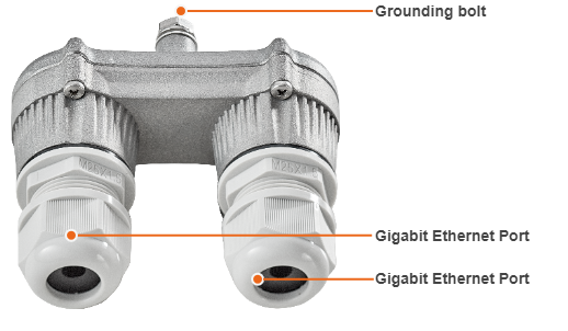
AUX-ODU-LPU-L is a bidirectional external outdoor lightning protection unit for Infinet Wireless systems designed to withstand the toughest conditions and protect the outdoor unit or the 3rd party networking equipment installed indoors from sudden power surges induced by lightning strikes. Despite the fact every Infinet wireless device has a built-in lightning protection. AUX-ODU-LPU-L, thanks to its superior GR-1089-grade protection, greatly reduces the risk of damage for the systems operating in harsh environments or difficult-to-reach locations. AUX-ODU-LPU-L is compatible with all Infinet Wireless devices.
NOTE
The device is not supplied by default and must be ordered separately.
| Parameter | Description | ||||||||
|---|---|---|---|---|---|---|---|---|---|
| Size and Weight |
| ||||||||
| Connectors and Interfaces |
| ||||||||
| Supported Ethernet Modes |
| ||||||||
| Water and Dust Protection |
| ||||||||
| Operating temperature range |
| ||||||||
| Ethernet pinout | Pin | 1 | 2 | 3 | 4 | 5 | 6 | 7 | 8 |
| Data pair | A+ | A- | B+ | C- | C+ | B- | D+ | D- | |
| Lightning Protection | In compliance with:
| ||||||||
Packing list
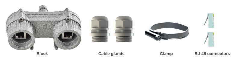
AUX-ODU-LPU-L is supplied with a worm clamp TORRO 40-60/9 C7 W4 DIN 3017. The clamp is made of stainless steel A4, width 9 mm, allows the installation on a mast with a diameter of 35 to 60 mm. In case of mast diameter more than 60 mm, a similar clamp (up to a 230 mm diameter) with a width of up to 12-13 mm can be used.
Lightning Protection Unit AUX-ODU-LPU-G
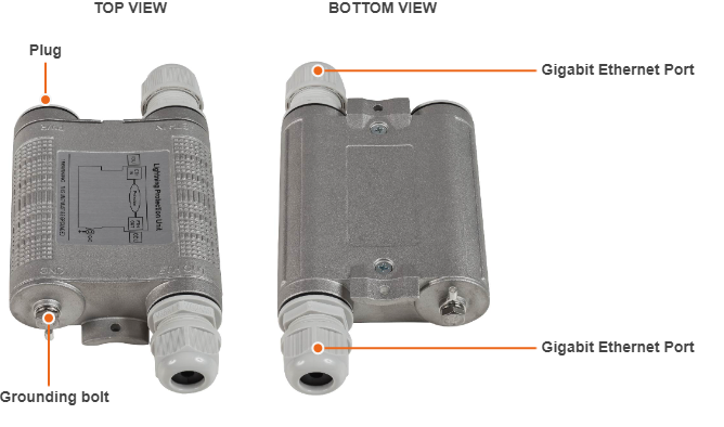
Optional indoor/outdoor Lightning Protection Unit for Infinet Wireless systems designed to withstand the toughest conditions and protect the outdoor or the indoor unit from sudden power surges induced by lightning strikes. It provides the same level of protection as AUX-ODU-INJ-G. AUX-ODU-LPU-G is compatible with all Infinet Wireless devices.
Despite the fact every Infinet Wireless unit has a built-in lightning protection, AUX-ODU-LPU-G, thanks to its superior GR-1089-grade protection, greatly reduces the risk of replacing damaged devices operating in harsh environments or difficult-to-reach locations.
NOTE
The device is not supplied by default and must be ordered separately.
| Parameter | Description | ||||||||
|---|---|---|---|---|---|---|---|---|---|
| Size and Weight |
| ||||||||
| Connectors and Interfaces |
| ||||||||
| Supported Ethernet Modes |
| ||||||||
| Water and Dust Protection |
| ||||||||
| Operating temperature range |
| ||||||||
| ETH IN and ETH OUT pin-out | Pin | 1 | 2 | 3 | 4 | 5 | 6 | 7 | 8 |
| Data pair | A+ | A- | B+ | C- | C+ | B- | D+ | D- | |
| Lightning Protection | In compliance with:
| ||||||||
Packing list
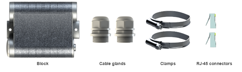
AUX-ODU-LPU-G is supplied with a worm clamp TORRO 40-60/9 C7 W4 DIN 3017 - 2 pcs. The clamp is made of stainless steel A4, width 9 mm, allows the installation on a mast with a diameter of 35 to 60 mm. In case of mast diameter more than 60 mm, a similar clamps (up to a 230 mm diameter) with a width of up to 12-13 mm can be used.
Synchronization Unit AUX-ODU-SYNC
AUX-ODU-SYNC is a TDD synchronization hub, which has been designed to provide a timing reference to Base Stations sectors of InfiMAN 2x2, InfiMAN Evolution families and InfiLINK 2x2 PRO devices. In combination with Infinet’s proprietary TDMA-based wireless architecture, AUX-ODU-SYNC completes the solution, providing TDD synchronization to its systems, both legacy and newly deployed.
TDD synchronization eliminates self-interference between multiple co-located units and enables frequency re-use within the same site. Infinet’s implementation supports not only intra-, but inter-site synchronization too, thanks to the fact that the timing reference is GNSS-based.
| Parameter | Description |
|---|---|
| Compatible models |
|
| GNSS receiver |
|
| GNSS antenna |
|
| Water and Dust protection |
|
| Consumption, W |
|
| Input voltage, VDC |
|
| PoE type |
|
| Interfaces and connectors |
|
| Compatible InfiNet Wireless power supplies |
|
| Temperature range |
|
| Size and Weight |
|
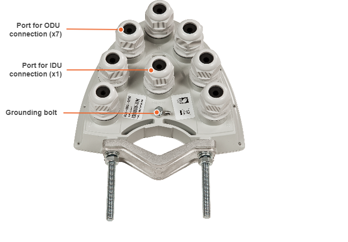
| Indicators | Indicators is located near the power port of AUX-ODU-SYNC:
|
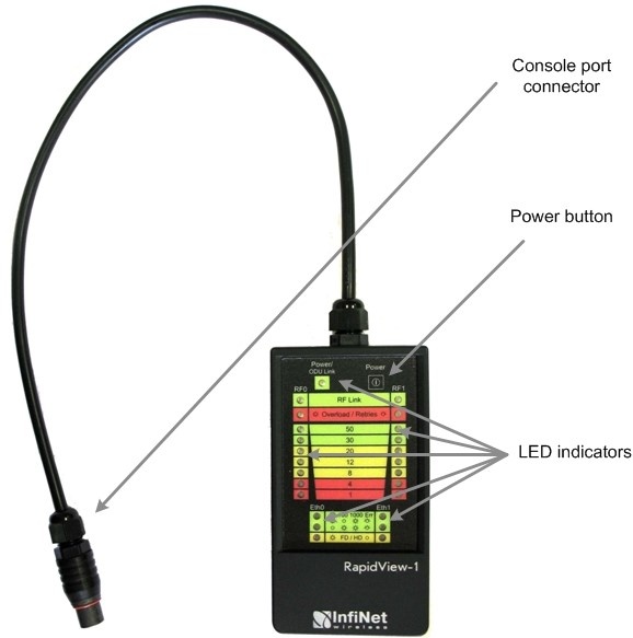
Alignment tool CAB-RV1
Device allows getting the following information:
- Radio link establishment indication
- Visual monitoring of radio signal levels
- Receiving retries information
- Diagnostic of RF and Ethernet interfaces.
How to use
- For turning RapidView-1 on simply push «Power button»
- Device LEDs will light up for 2 seconds
- Device will perform constant tries to connect to ODU. If device’s power is normal Power/ODU connection LED (1) will blink 1 time per second. If device’s power is low LED 1 will blink 4 times per second in turn with not lighting intervals.
- Once ODU link is established LED 1 stops blinking (if power is normal) and device’s interfaces status are shown by LEDs 2-6.
- 1 time per second device updates its status output.
- If ODU link will be broken LEDs 2-6 will go out after 2 seconds and LED 1 will start blinking 1 time per second.
Diagnostic device connection to ODU should be done via console port of the ODU. Once link is up between ODU and diagnostic device the following record is put in ODU system log:
- Connected test unit. Begin service communication over console
- Test unit detected: rf0 – rf5.0
Exact radio interface names depend on wireless equipment configuration.
When diagnostic device is unplugged from the following record is put in ODU system log:
Test unit disconnected. Return to normal console mode.
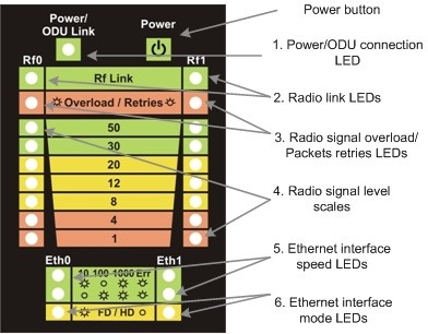
LEDs modes description
ODU status monitoring via diagnostic device is performed by its LEDs indication. LEDs modes and ODU status correspondence is shown in the following table
| LED | Function | |||||||||||||||
|---|---|---|---|---|---|---|---|---|---|---|---|---|---|---|---|---|
| Power/ODU connection LED | Shows diagnostic device power status and diagnostic device-ODU connection status:
| |||||||||||||||
| Radio link LEDs | Shows whether radio link is established on certain ODU’s radio interface:
What ODU’s radio interface to show by what column RF0 or RF1 is chosen by the following way:
For example, there are the following radio interfaces on ODU: Rf5.0, rf5.1. Then for RF0 column rf5.0 will be taken, for RF1 — rf5.1. When no radio link then LEDs 2-4 are not lighting | |||||||||||||||
| Radio signal overload/Packets retries LEDs | Shows receiving radio signal level overload and number of packet retries information:
If certain radio interface (radio module) is not present on the device then all corresponding LEDs of this radio interface is off. If ODU has certain radio interface but it is not activated (for example, not entered «mint rf5.0 start» command) then LED 3 is blinking 1 time per second whereas LEDs 2 and 4 are not lighting. If ODU has certain radio interface but it is not activated (for example, not entered «mint rf5.0 start» command) then LED 3 is blinking 1 time per second whereas LEDs 2 and 4 are not lighting. If ODU has certain radio interface activated («mint rf5.0 start» command entered) then LED 3 is blinking 4 times per second whereas LEDs 2 and 4 are not lighting | |||||||||||||||
| Radio signal level scales | Shows receiving signal level of the established radio link. Each LED can be in 3 modes:
| |||||||||||||||
| Ethernet interface data rate LEDs | Shows data rate of the corresponding Ethernet interface. There are 2 LEDs for each Ethernet interface (Eth0 and Eth1)
| |||||||||||||||
| Ethernet interface mode LEDs |
IF Ethernet connection is established but corresponding ODU’s interface is not enabled then LEDs 5, 6 indicate connection configuration by blinking 1 time per second |