Successfully pass the free certification exam at IW Academy and become an Infinet Certified Engineer.
One of the most common situations when we configure more than one radio profile for a CPE is when it can establish a wireless link to more than one base station, depending on the link quality. The CPE can switch the communication with other base stations in order to be operational and to provide services in the situation when the wireless link with the main BS is dropped.
For this example, we have three units with the default configuration.
- Step 1
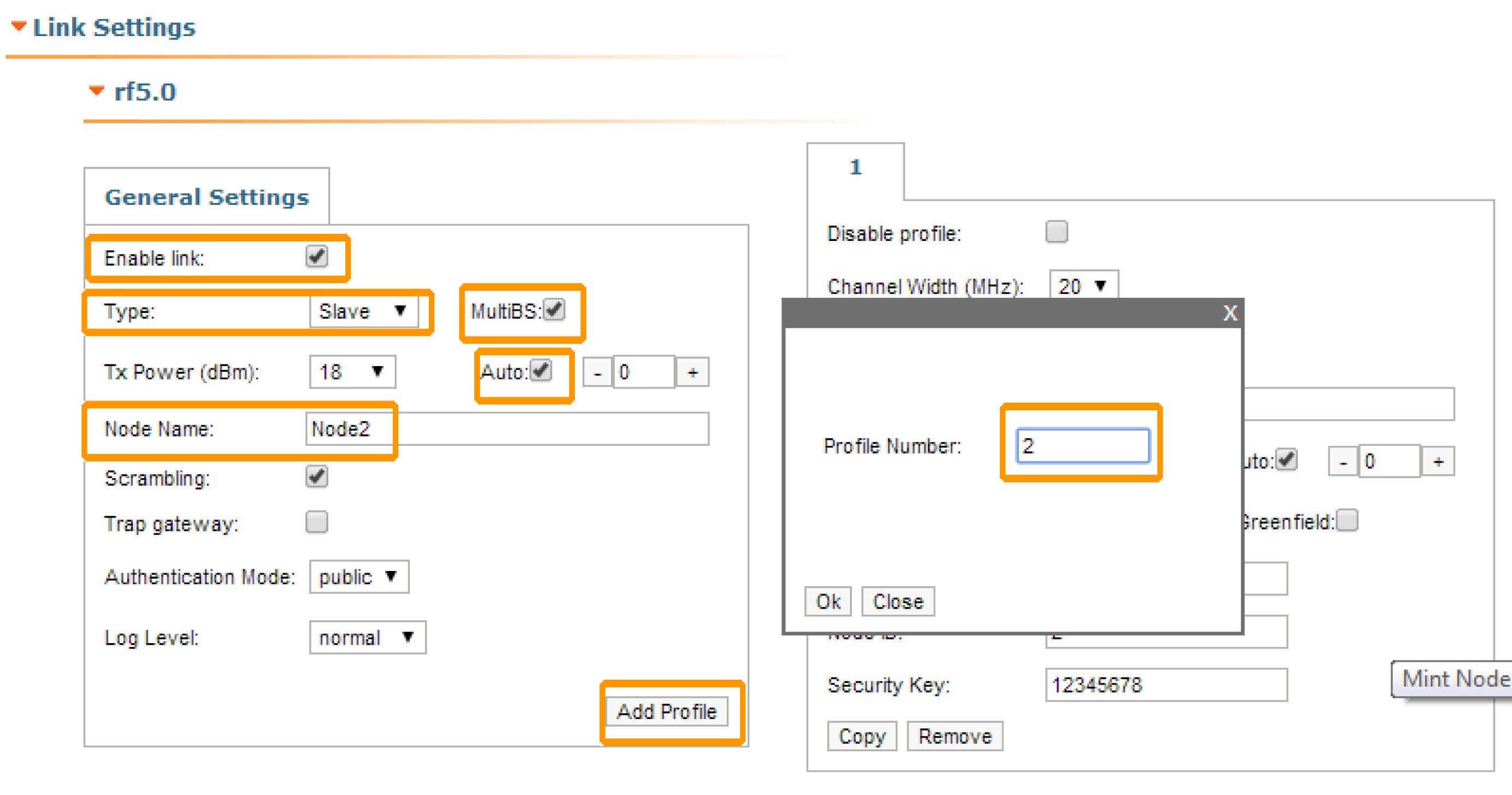
After the authentication on the first unit, let’s go to "Basic Settings" → "Link Settings" menu and let’s do the following configuration in "General Settings" section:
- Enable link: selected
- Type: slave (for the CPE)
- MultiBS: selected (this option tells the CPE to search automatically for another BS when the link with the main BS is lost)
- Auto Tx Power: selected
- Node name: Node2
Click the «Add Profile» button, set the profile number 2 and then click the «OK» button:
Thus, the second radio profile is created with the same settings as the first profile (except the frequency, which is set to “Auto”).
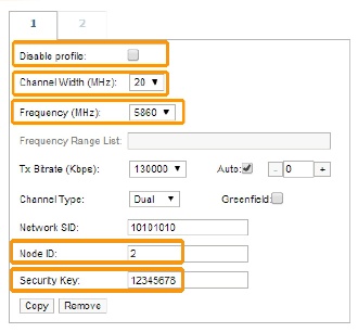
Let’s do the following configuration for the first radio profile:
- Disable profile: unselected
- Channel Width: 20 MHz
- Frequency: 5860 MHz
- Node ID: 2
- Security Key: 12345678
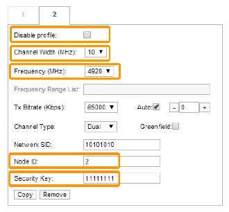
Let’s do the following configuration for the second radio profile:
- Disable profile: unselected
- Channel Width: 10 MHz
- Frequency: 4920 MHz
- Node ID: 2
- Security Key: 11111111
We have to click the «Apply» button at the bottom of the page, in order to save the settings performed in "Link Settings" menu.
- Step 2
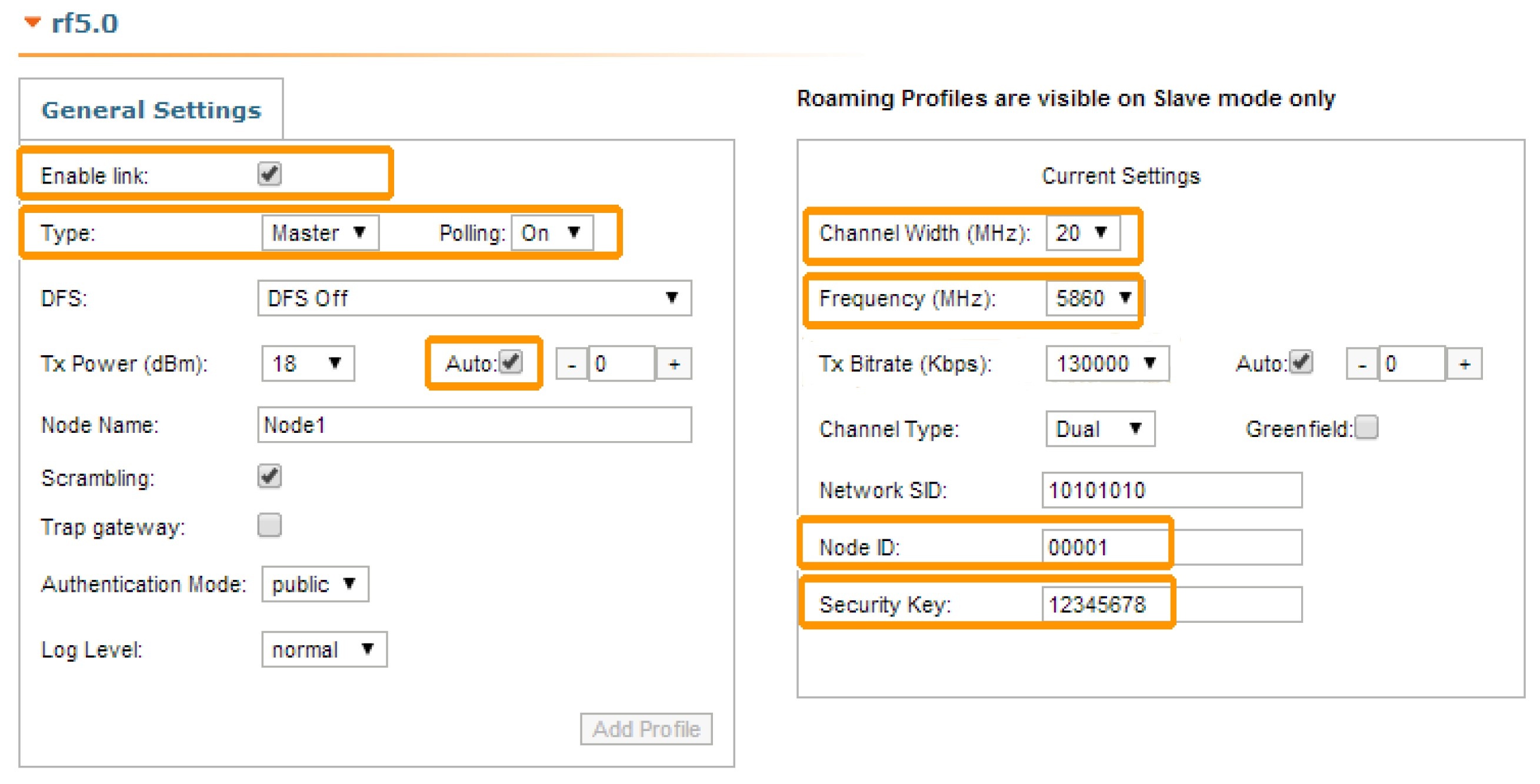
Let’s now connect to the second unit and after the authentication step, let’s go to "Basic Settings" → "Link Settings" menu and let’s do the following configuration in the "General Settings" section:
- Enable link: selected
- Type: master (for the BS configuration)
- Polling: On
- Auto Tx Power: selected
- Node name: Node1
Let’s do the following configuration in the "Current Settings" section:
- Channel Width: 20 MHz
- Frequency: 5860 MHz
- Node ID: 1
- Security Key: 12345678
Click the «Apply» button at the bottom of the page, in order to save the settings performed in the "Link Settings" menu.
- Step 3
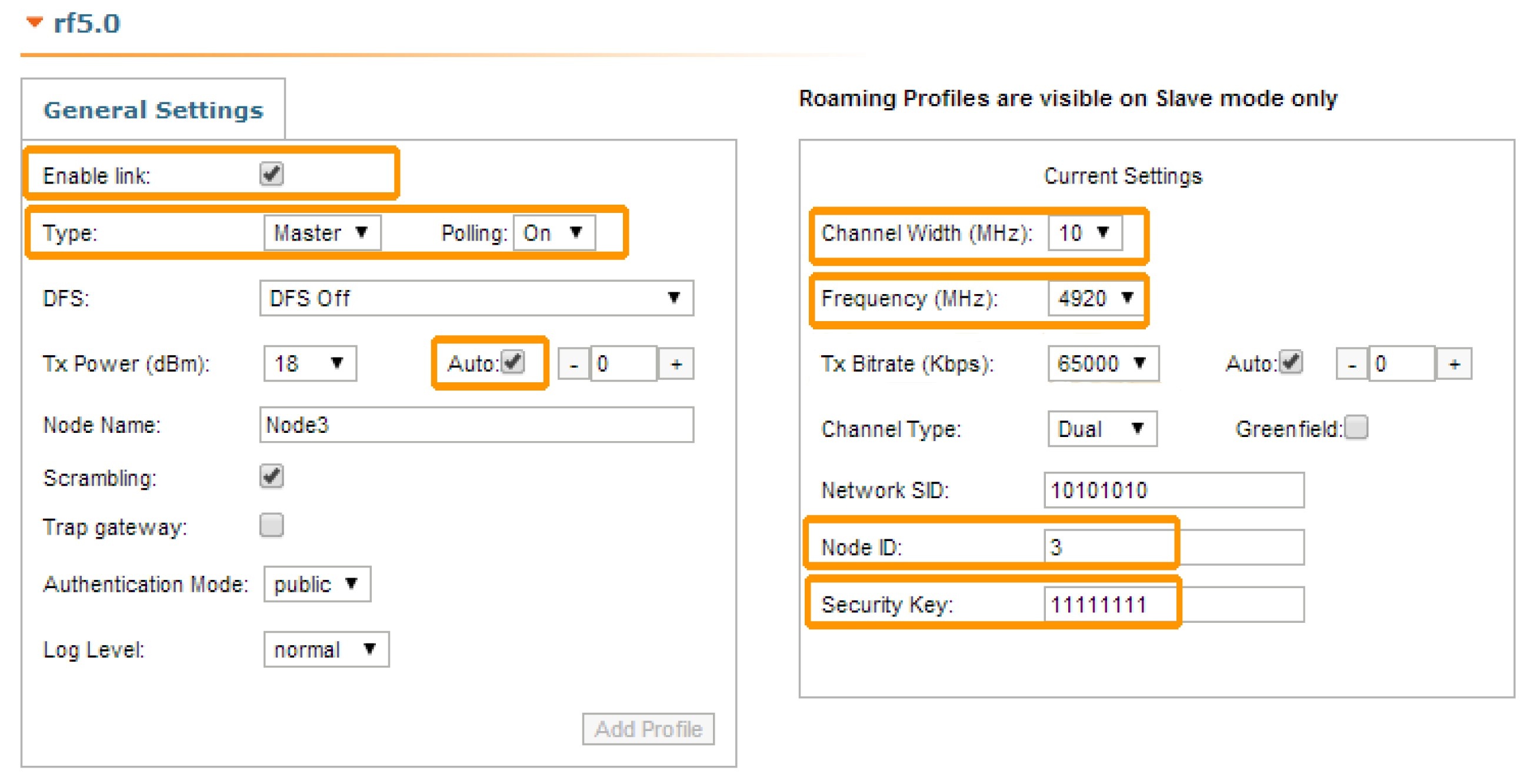
Let’s now connect to the third unit and after the authentication step, let’s go to "Basic Settings" → "Link Settings" menu and let’s do the following configuration in "General Settings" section:
- Enable link: selected
- Type: master (for the BS configuration)
- Polling: On
- Auto Tx Power: selected
- Node name: Node3.
Let’s do the following configuration in the "Current Settings" section:
- Channel Width: 10 MHz
- Frequency: 4920 MHz
- Node ID: 3
- Security Key: 11111111.
Click the «Apply» button at the bottom of the page, in order to save the settings performed in the "Link Settings" menu.
We have now two base stations (nodes 1 and 3) configured and one CPE (node 2) with two radio profiles configured: profile 1 has the radio parameters of the BS1 and profile 2 has the radio parameters of the BS2.
We can see now that the CPE can establish a wireless link with any of the two base stations, depending on the link quality.