Successfully pass the free certification exam at IW Academy and become an Infinet Certified Engineer.
One of the most common solutions to separate data traffic from the BS to the CPEs and vice versa is to create VLAN filters within different switching groups. For the management traffic, we have to create a separate switching group and VLAN. In this case, the CPEs cannot communicate between them and they cannot access the management VLAN:
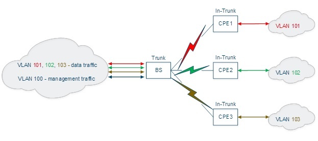
For this example, we have four InfiNet Wireless R5000 units with the default factory configuration and we are going to configure one of them to work as BS and the other three to work as CPEs (in this example, from the traffic point of view).
- Step 1
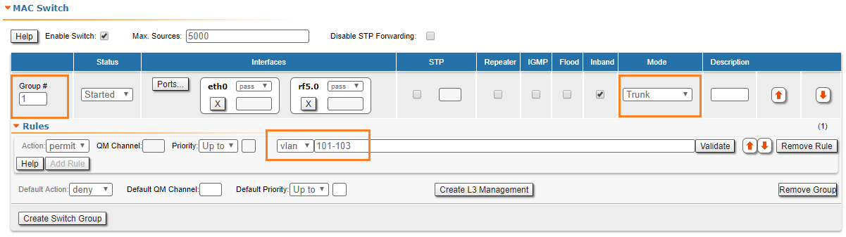
Let’s log in to one of the four units and configure it as BS. We have to go to "Basic Settings" → "MAC Switch" section and modify the configuration for the default Switch Group #1 in order to accommodate the traffic from all CPEs:
- Select Trunk mode for the Switch Group #1.
- Add a new rule for this switch group and select VLAN mode for it.
- Configure all VLANs that must be processed within this Switch Group #1: let's configure VLAN101, VLAN102 and VLAN103. Please note that PCAP expressions cannot be used in this case.
- Step 2
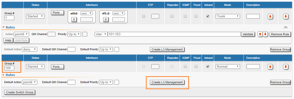
We have to create a second Switch Group for the management traffic to the unit:
- Click the «Create Switch Group» button and then enter a Switch Group number in the pop-up window (we strongly recommend using your management VLAN number as the management Switch Group number to avoid confusion).
- Click the «Create L3 Management» button to create SVI interface for the management traffic.
- Step 3
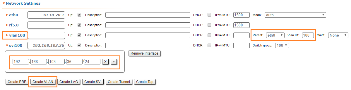
We have to assign an IP address to SVI interface and create VLAN interface:
- In the "Network Settings" section, assign an IP address to the automatically created SVI interface.
- Click the «Create VLAN» button and set the management VLAN number.
- Set Ethernet interface as parent to VLAN and configure Vlan ID.
- Step 4
The management traffic in our network belongs to VLAN 100 and therefore, it is tagged. In order to access the unit through the management network, VLAN interface should be added to the management group.
- Click the «Ports» button and add VLAN and RF interfaces.
- Step 5
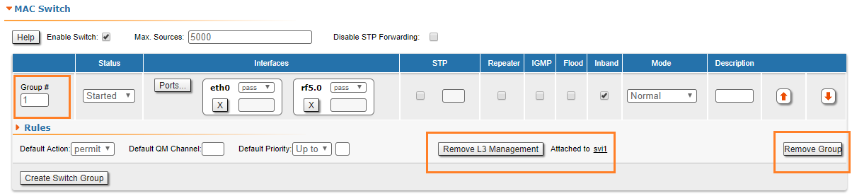
Let’s log in to one of the remained three units and configure it as CPE (in this example, from the traffic point of view). We have to configure two Switch Groups, as well: one for the data traffic and another one for the unit management. However, the default Switch Group #1 cannot be used for any of these purposes, so we are going to remove it in order to simplify the configuration:
- Go to the "Basic Settings" → "MAC Switch" section.
- Click the «Remove L3 Management» button on the Switch Group #1 subsection and then click the «OK» button.
- Click the «Remove Group» button on the Switch Group #1 subsection and then click the «OK» button.
- Step 6a
We have to create another Switch Group that will handle all the data traffic that crosses through the CPE. The data traffic received by the CPE could be untagged (the scenario covered in this step) or tagged (the scenario covered in Step 6b).
The process is the same as the one described in the previous sections, however, there are two important differences:
- The Switch Group number must correspond with the VLAN number used by this client. We are going to configure VLAN 101 for the CPE 1 and the Switch Group #101.
- The Switch Group operation mode must be set to “In-Trunk”. This mode requires a numerical parameter which is the Switch Group number (set in the BS) containing the necessary VLAN corresponding to the CPE. In our case, the client data traffic that goes to the BS from the upstream equipment is placed into Switch Group #1, so "In-Trunk" mode parameter must be set to 1.
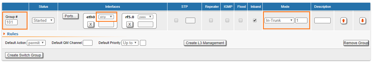
- The Ethernet interface must act as an access port in this scenario, so the VLAN tag must be stripped (removed) from all egress packets and all inbound traffic should be tagged.
We are going to perform the following configuration:
- Click the «Create Switch Group» button.
- Configure Switch Group 101 in the pop-up window.
- Click the «Ports» button.
- Select both Ethernet and RF interfaces in the pop-up window and then click the «OK» button.
- Select strip from the drop-down menu of the eth0 operation modes to strip the VLAN tag.
- Select In-Trunk mode, set the In-Trunk value to 1, as our BS has the Switch Group 1 configured to process all CPEs data traffic.
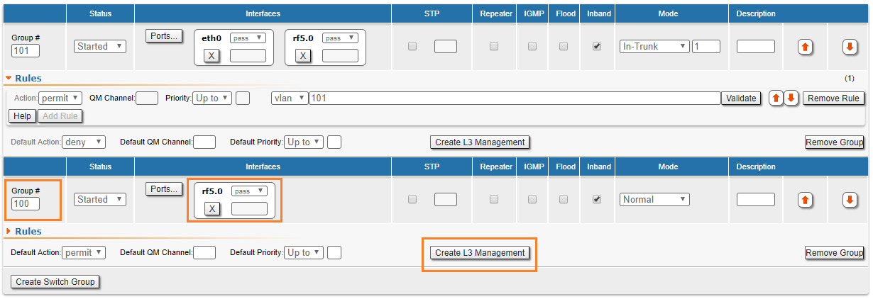
- Step 6b
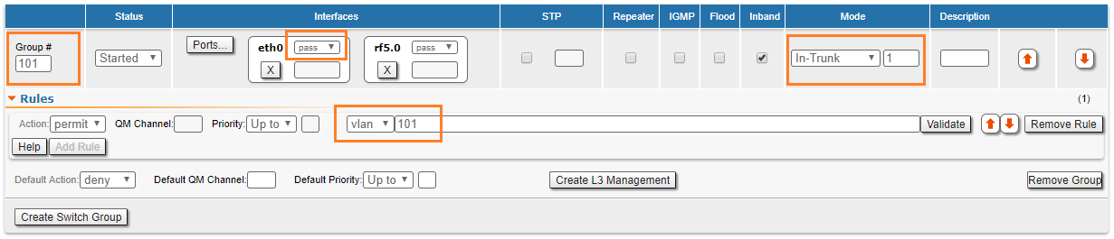
The Ethernet interface must act as a trunk port in this scenario, so we have to create a filter rule for the Switch group #101.
In case the client has multiple VLANs, a separate Switch Group should be created for each VLAN.
We are going to perform the following configuration:
- Click the «Create Switch Group» button.
- Configure Switch Group 101 in the pop-up window.
- Click the «Ports» button.
- Select both Ethernet and RF interfaces in the pop-up window and then click the «OK» button.
- Select In-Trunk mode, set the In-Trunk value to 1, as our BS has the Switch Group 1 configured to process all CPEs data traffic.
- Open the Rules zone and click the «Add Rule» button.
- Select VLAN mode and configure the VLAN 101 that must pass within this Switch Group. Note that PCAP expressions cannot be used in "trunk/in-trunk mode".
- Step 7
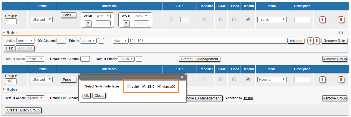
For the management traffic to the CPE, we have to configure a dedicated Switch Group, SVI interface.
- Click the «Create Switch Group» button.
- Configure Switch Group 100 in the pop-up window (we strongly recommend using your management VLAN number as a management Switch Group number to avoid confusion).
- Click the «Ports» button, select RF interface only and click «OK».
- This Switch Group contains only the RF interface, as the management interface needs to be accessible only by radio.
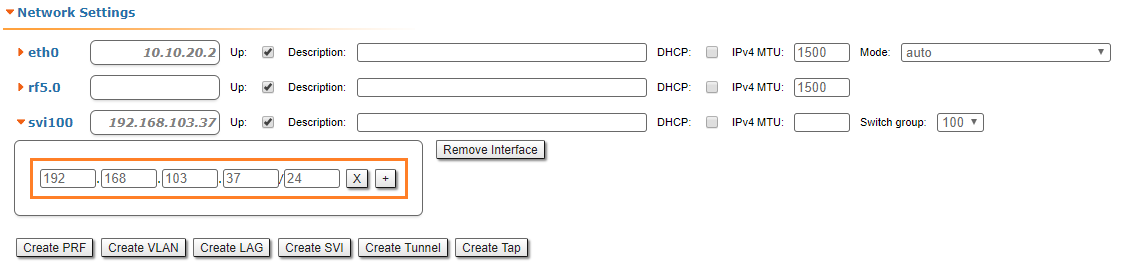
- Step 8
We have to create an SVI interface for the management traffic and to assign an IP address:
- Click the «Create L3 Management button» button.
- Assign an IP address to the automatically created SVI interface.
Please repeat the steps from 5 to 8 in order to configure the other two CPEs. Configure Switch groups 102 and 103, filter rules for the VLANs 102 and 103 (in case of tagged traffic) and management IP addresses on svi100 interfaces.
- The BS configuration file, as a result of the settings described in steps above:
#System parameters
#Factory password mode: single
sys name Node1
sys prompt Node1
sys user admin
setpass $1$5ieEa$9sTTnyEx4/1thTlmfb/S6.

#Radio module parameters
rf rf5.0 grid 40 4930-5930/20
rf rf5.0 grid 20 4920-5940/20
rf rf5.0 grid 10 4915-5945/5
rf rf5.0 grid 5 4915-5945/5
rf rf5.0 band 20
rf rf5.0 mimo
rf rf5.0 freq 5860 bitr 130000 sid 10101010 burst
rf rf5.0 txpwr -5 pwrctl distance auto(4)

#DFS configuration
dfs rf5.0 dfsoff
dfs rf5.0 freq auto
dfs rf5.0 cot off

#Interfaces parameters
ifc lo0  127.0.0.1/32
ifc eth0 media auto mtu 1500 up
ifc eth0 10.10.20.1/24
ifc rf5.0 mtu 1500 up
ifc svi100 mtu 1500 up
        # group 100
ifc svi100 192.168.103.36/24
ifc vlan100 mtu 1500 up
ifc vlan100 vlan 100 vlandev eth0

#QoS manager
qm option rtp dot1p notos noicmp notcpack nostrict

#MINT configuration
mint rf5.0 -name "Node1"
mint rf5.0 -nodeid 00001
mint rf5.0 -type master
mint rf5.0 -mode fixed
mint rf5.0 -key "12345678"
mint rf5.0 -scrambling
mint rf5.0 -autobitrate
mint rf5.0 -minbitrate 13000
mint rf5.0 -hiamp 2 -loamp 0
mint rf5.0 -log
mint rf5.0 prof 1 -freq auto -sid 10101010 -bitr 130000 -band 20 \
			-nodeid 22363 -type slave -netid 0 \
			-minbitr 13000 -autobitr -mimo \
			-key "12345678"
mint rf5.0 -roaming leader
mint rf5.0 -authmode public
mint rf5.0 -airupdate passive normal
mint rf5.0 -rcmdserver enabled
mint rf5.0 poll start
mint rf5.0 start

#MAC Switch config
switch list LST1 numrange add 101-103

switch group 1 add 1 eth0 rf5.0
switch group 1 vlan LST1
switch group 1 trunk on
switch group 1 start
switch group 100 add 2 vlan100 rf5.0
switch group 100 start
     # group 100 attached to 'svi100'

switch start

#Switch Virtual Interface config
svi 100 group 100

#WEB configurator
webcfg start

#LLDP parameters
lldp eth0 enable txrx
- The CPE1 configuration file, as a result of the settings described in steps above (the trunk port scenario):
#System parameters
#Factory password mode: single
sys name Node2
sys prompt Node2
sys user admin
setpass $1$TC3kB$oILIriOiwU/knH3a5EkH70

#Radio module parameters
rf rf5.0 band 20
rf rf5.0 mimo
rf rf5.0 freq 5860 bitr 130000 sid 10101010 burst
rf rf5.0 txpwr 10 pwrctl distance auto(4)

#DFS configuration
dfs rf5.0 dfsonly

#Interfaces parameters
ifc lo0 127.0.0.1/32
ifc eth0 media auto mtu 1500 up
ifc eth0 10.10.20.2/24
ifc rf5.0 mtu 1500 up
ifc svi100 mtu 1500 up
            # group 100
ifc svi100 192.168.103.36/24
ifc vlan100 mtu 1500 up
ifc vlan100 vlan 100 vlandev eth0

#QoS manager
qm option rtp dot1p notos noicmp notcpack nostrict

#MINT configuration
mint rf5.0 -name "Node2"
mint rf5.0 -nodeid 00002
mint rf5.0 -type slave
mint rf5.0 -mode fixed
mint rf5.0 -key "12345678"
mint rf5.0 -scrambling
mint rf5.0 -autobitrate
mint rf5.0 -minbitrate 13000
mint rf5.0 -hiamp 2 -loamp 0
mint rf5.0 -log
mint rf5.0 prof 1 -freq 5860 -sid 10101010 -bitr 130000 -band 20 \
			-nodeid 00002 -type slave -netid 0 \
			-minbitr 13000 -autobitr -mimo \
			-key "12345678"
mint rf5.0 -roaming enable
mint rf5.0 -authmode public
mint rf5.0 -airupdate passive normal
mint rf5.0 -rcmdserver enabled
mint rf5.0 start

#MAC Switch config
switch group 101 add 1 eth0 rf5.0
switch group 101 vlan 101
switch group 101 in-trunk 1
switch group 101 start

switch group 100 add 2 rf5.0
switch group 100 start
     # group 100 attached to 'svi100'

switch start

#Switch Virtual Interface config
svi 100 group 100

#WEB configurator
webcfg start

#LLDP parameters
lldp eth0 enable txrx

#end