Successfully pass the free certification exam at IW Academy and become an Infinet Certified Engineer.
Device Placement
When selecting the placement of the wireless devices for a PtP link, in order to obtain the maximum link range and performance, LOS must be clear for the path between the two devices.
The radio beam is an invisible electromagnetic wave and it is not as thin as, for example, a light (or laser) beam. The main energy in a radio beam is concentrated along the straight line between the two antennas, inside an area having the shape of an ellipsoid (or a rugby ball). This area is called the 1st Fresnel zone and its exact form and size depend upon the frequency and the signal's propagation path length.
If most of the 1st Fresnel zone is obstructed, a major part of the radio wave’s electromagnetic energy is lost, which leads to a severe signal quality degradation and, as a result, to decreased coverage range or performance.
Below is an incomplete list of possible obstructions on the signal's propagation path:
- Neighboring buildings
- Trees
- Bridges
- Power lines
To obtain the best results, it is necessary to perform a precise analysis of the signal's propagation path and of the possible obstructions that may obstruct the 1st Fresnel zone.
NOTE
For radio planning and path profile analysis, both the terrain model and clutter layer of the area are required. These are typically provided by professional mapping vendors. For details, please contact InfiNet Wireless.
Here are some general recommendations for the antenna placement:
- Try to keep the LOS clear of obstructions. In case of installations over vegetation and forest, make sure the direct LOS stays above the trees; in urban environments - above the tallest buildings along the radio path.
- The influence of trees can be variable, depending on seasons (ice, dew, leaves). Keep in mind that, during spring and summer, leaves can absorb high levels of radio energy. Therefore, when installing during the cold season, over forests and trees without leaves, try to achieve a higher fade margin.
- Before installation, make sure the devices are located outside the area of water streams and splashes formation, which can affect the enclosure for a long time.
- Proximity to other antennas should be avoided (the recommended distance is at least 2 meters between the edges of the antennas).
- Install the devices at a distance of at least 100-150 meters from power lines having a voltage higher than 35 kV.
- Reflecting surfaces should be considered (buildings with reflective windows, water surfaces or wet grounds). These can be useful in NLOS situations, where there is no direct clear path between the 2 antennas, so the radio signal needs to be reflected off a surface. However, the reflecting surfaces can also decrease the signal's quality when encountered along a clear LOS link, because of fading caused by multipath propagation.
- When installing antennas over the water, tune the height bracket within a 1-3 meters range variation, because it can yield significant signal level variations due to multipath fading.
- If seasonal changes influence the signal's quality, then the most probable reasons would be either that the connectors are not protected well enough from humidity, or that the cables, connectors or antennas are covered by vegetation during summer or by ice during winter.
Mounting Types
Pole Mounting
The installation of the antenna is performed on a special facility called the antenna pole. The pole is used for strong antenna tightening at the installation site. Poles might differ depending on the installation requirements.
Poles with Stretching
Usually this kind of poles are used when installing antennas on a flat surface and allow the installer to raise the antenna at a significant height for providing optimal conditions for the signal propagation.
Wall Mounting
This kind of mounting is used when there is no need to elevate the antenna above the rooftop and it is possible to mount the antenna on a wall. This installation is significantly simpler than the implementation with poles.
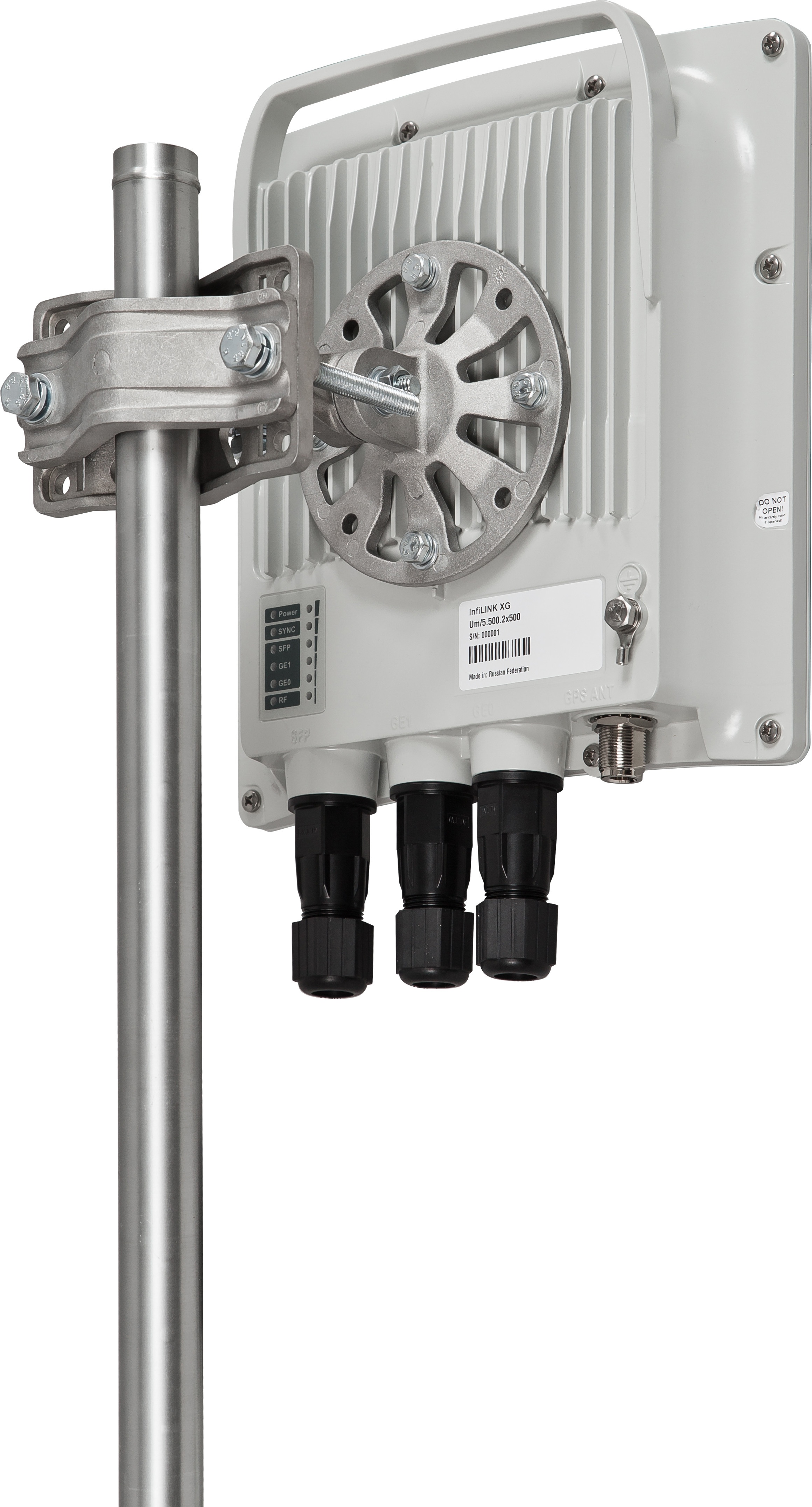
Pole Requirements
Easy access and sufficient mechanical durability of the pole should provide quick and reliable fastening in conditions of high wind loads. The poles should have a round profile for easing the azimuth adjustment. The typical pole diameter is 30 to 85 mm.
Spectral aggregation of two wireless links
Spectral aggregation should be taken into account when planning composite backhauling links, when installing devices in close proximity to each other (on the same pole) or in order to implement redundancy and link aggregation. For more information, proceed with the "Link aggregation, balancing and redundancy" article. The devices located close to each other can cause mutual interference. Do not ignore the spectral aggregation rules, otherwise it can lead to a degradation of the wireless links.
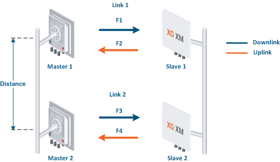
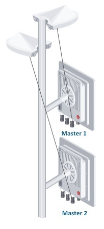
Let's look at an example with two wireless links:
- Link 1 is established between the Master 1 and Slave 1 devices. Link 2 between Master 2 and Slave 2.
- Links 1 and 2 are parallel to each other. The coverage areas of the Master 1 and Master 2 devices intersect and that leads to mutual interference in case of applying improper diversity methods
- The Slave 1 and Slave 2 devices can interfere with Master 2 and Master 1. However, due to the significantly higher mutual interference between Master 1 and Master 2, the interference from slave devices can be neglected.
In order to avoid the mutual interference for collocated devices, it is necessary to implement space diversity or to configure a sufficient guard interval between the used frequency bands.
This article describes space and frequency diversity in both scenarios when TDD synchronization is used or when it's not used.The InfiLINK XG and InfiLINK XG 1000 families of devices have a built-in GNSS receiver, which along with the connected external ANT-SYNC antenna allows to achieve TDD synchronization based on the signal received from the satellite system. TDD (time division duplex) synchronization assumes that data is received and transmitted by the devices at strictly allocated time intervals, in accordance with the radio frame period and with the downlink/uplink ratio settings. By default, only the slave device transmission is synchronized using the master's internal synchronization source. When the synchronization mode based on GNSS is enabled, the devices will receive a synchronization signal from the global navigation system and will transmit data simultaneously with the other InfiLINK XG devices on which the synchronization mode is activated.
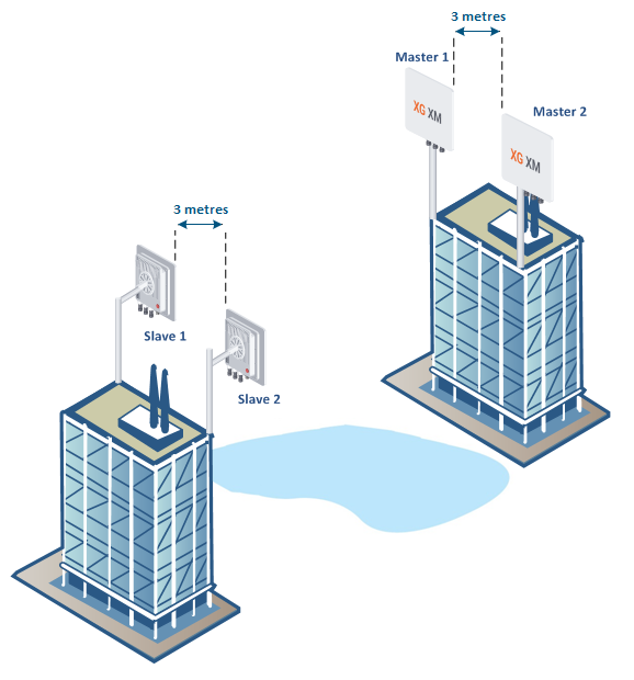
Space diversity
Without synchronization
In case that the GNSS based synchronization is not used, the minimal space diversity between edges of the antennas on the same mast should be at least three metres in the horizontal or vertical planes.
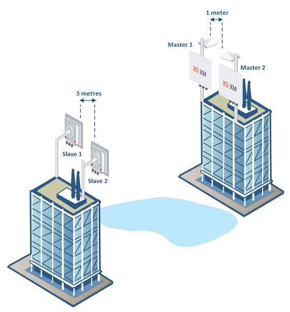
With synchronization
In case that the synchronization is enabled, in order to achieve the minimum mutual interference between the Master 1 and Master 2 devices, the distance can be reduced to 1 meter.
Frequency diversity
Without synchronization
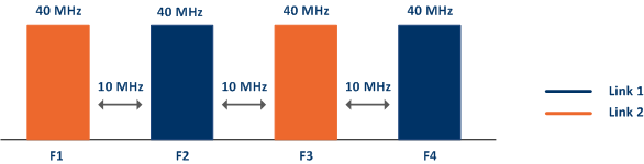
When synchronization is not used between the Master 1 and Master 2 devices, the guard interval values for each channel width that are shown in the table should be used. Increasing the guard interval beyond the recommended values does not lead to a significant improvement in the RSSI.
| Channel width, MHz | Guard interval, MHz |
|---|---|
| 40 | 10 |
| 20 | 10 |
| 10 | 5 |
An example of frequency diversity for a 40 MHz channel width:
With synchronization
The GNSS synchronization of Master 1 and Master 2 allows to reduce the size of the guard interval. The minimum noise level is required, as well the interference level from the other Slave device should not exceed the RSSI level received from its own Slave device. However, we do not recommend reducing the guard interval below the values shown in the table above.
NOTE
During the configuration of the InfiLINK XG 1000 family, the minimum necessary guard interval between the center frequencies of the “Carrier 0” (first radio module) and “Carrier 1” (second radio module) should be set to:
| Channel width, MHz | Guard interval, MHz |
|---|---|
| 10 | 20 |
| 20 | 40 |
| 40 | 80 |
GNSS based synchronization settings
To perform GNSS based synchronization, each InfiLINK XG/InfiLINK XG 1000 master must be connected to an external GLONASS/GPS antenna - ANT-SYNC.
Identical radio frame period and downlink ratio values must be set for each link in order to make sure that the synchronization works properly. The automatic downlink ratio selection is not allowed.
NOTE
The ANT-SYNC antenna is not included in the standard packing list. For more information about this antenna, proceed to the ANT-SYNC article.
Configuration via WEB interface
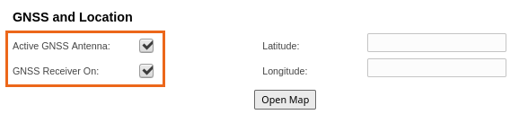
To enable synchronization, go to the "General" - "GNSS and Location" section, check the boxes next to the "Active GNSS Antenna" and "GNSS Receiver On" options.
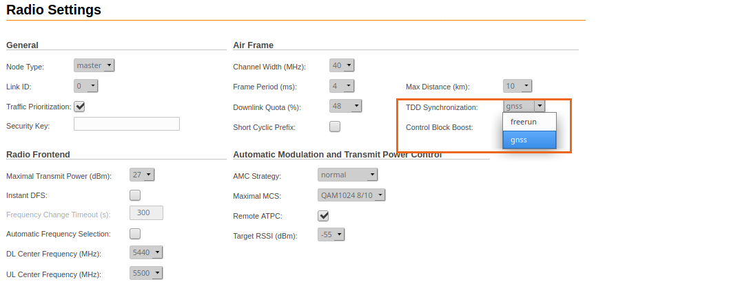
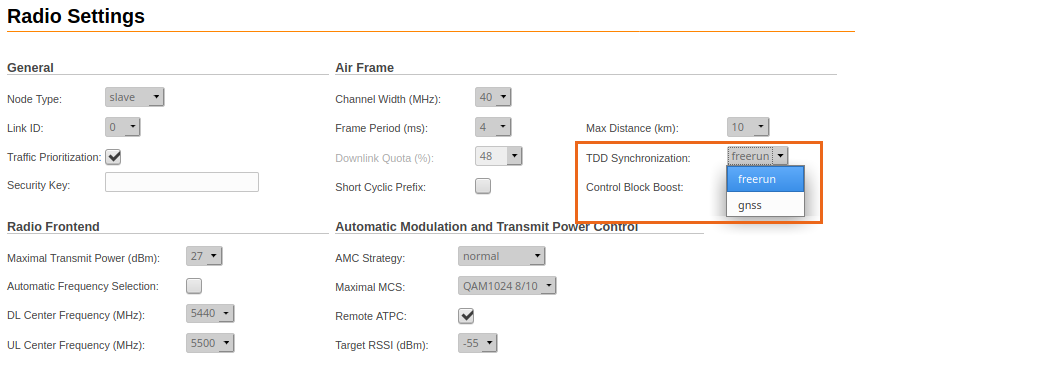
Go to the "Radio" - "TDD Synchronization" section, select the "gnss" synchronization method from the drop-down list. Click on the "Apply" button. GNSS synchronization must be enabled on each master device. Slave devices must remain in freerun mode and will receive synchronization from the master's GNSS receiver.
CAUTION
In case there is no satellite available, the link will not be established in the "gnss" synchronization mode.
Master device configuration:
Slave device configuration:
For more details on the radio parameters's configuration proceed to the "Radio" TUM section.
Configuration via CLI
The synchronization should be configured only at the master device.
Enable the GNSS receiver by entering the "gps start" command. To display information about the GNSS receiver statistics use the "gps coordinates" command. The "HDOP" parameter value should be 1,5 or higher, otherwise the synchronization won't work properly.
#1> gps start
#1> gps coordinates
Satellites: 8
LAT/LONG:   56.811911/60.547041
Altitude:   275.89
HDOP:       0.92
FIX:        3D, GLONASS
Total GPS time: 17:43:19
Total nonvalid time: 00:00:01(0%)
Number of losses: 0
Now coordinates are valid last 17:43:18
Satellites histogram:
       ^
       |
   2.0 +
       |
   3.0 +
       |
   4.0 +
       |
   5.0 +
       | <1%
   6.0 +
       | 1%
   7.0 +
       |||||||||||||||||||||||||||||||||||||||||||||||||| 99%
       v
SATmin= 5 SATmax= 10
Enable GNSS based TDD synchronization by using the "xg -tdd-sync-src gnss" command. To apply the settings, the device must be rebooted. Save the configuration using the "config save" command and then to reboot the device enter the "restart" command and confirm by typing "y".
#1> xg -tdd-sync-src gnss
xg: there are settings that can be applied only after reboot
*tdd-sync-src
#1> config save

Current configuration saved successfully

#1> restart
Reboot... Are you sure [y/n] ?y

System restarted