Successfully pass the free certification exam at IW Academy and become an Infinet Certified Engineer.
Device Placement
When selecting the placement of the wireless devices for a PtP link, in order to obtain the maximum link range and performance, LOS must be clear for the path between the two devices.
The radio beam is an invisible electromagnetic wave and it is not as thin as, for example, a light (or laser) beam. The main energy in a radio beam is concentrated along the straight line between the two antennas, inside an area having the shape of an ellipsoid (or a rugby ball). This area is called the 1st Fresnel zone and its exact form and size depend upon the frequency and the signal's propagation path length.
If most of the 1st Fresnel zone is obstructed, a major part of the radio wave’s electromagnetic energy is lost, which leads to a severe signal quality degradation and, as a result, to decreased coverage range or performance.
Below is an incomplete list of possible obstructions on the signal's propagation path:
- Neighboring buildings
- Trees
- Bridges
- Power lines
To obtain the best results, it is necessary to perform a precise analysis of the signal's propagation path and of the possible obstructions that may obstruct the 1st Fresnel zone.
NOTE
For radio planning and path profile analysis, both the terrain model and clutter layer of the area are required. These are typically provided by professional mapping vendors. For details, please contact InfiNet Wireless.
Here are some general recommendations for the antenna placement:
- Try to keep the LOS clear of obstructions. In case of installations over vegetation and forest, make sure the direct LOS stays above the trees; in urban environments - above the tallest buildings along the radio path.
- The influence of trees can be variable, depending on seasons (ice, dew, leaves). Keep in mind that, during spring and summer, leaves can absorb high levels of radio energy. Therefore, when installing during the cold season, over forests and trees without leaves, try to achieve a higher fade margin.
- Before installation, make sure the devices are located outside the area of water streams and splashes formation, which can affect the enclosure for a long time.
- Proximity to other antennas should be avoided (the recommended distance is at least 2 meters between the edges of the antennas).
- Install the devices at a distance of at least 100-150 meters from power lines having a voltage higher than 35 kV.
- Reflecting surfaces should be considered (buildings with reflective windows, water surfaces or wet grounds). These can be useful in NLOS situations, where there is no direct clear path between the 2 antennas, so the radio signal needs to be reflected off a surface. However, the reflecting surfaces can also decrease the signal's quality when encountered along a clear LOS link, because of fading caused by multipath propagation.
- When installing antennas over the water, tune the height bracket within a 1-3 meters range variation, because it can yield significant signal level variations due to multipath fading.
- If seasonal changes influence the signal's quality, then the most probable reasons would be either that the connectors are not protected well enough from humidity, or that the cables, connectors or antennas are covered by vegetation during summer or by ice during winter.
When planning the wireless device placement for PtMP connections, one must consider the necessity of a circular or sector coverage areas. In this respect, it is not recommended to use omni-directional antennas when sector antennas can be used.
Mounting Types
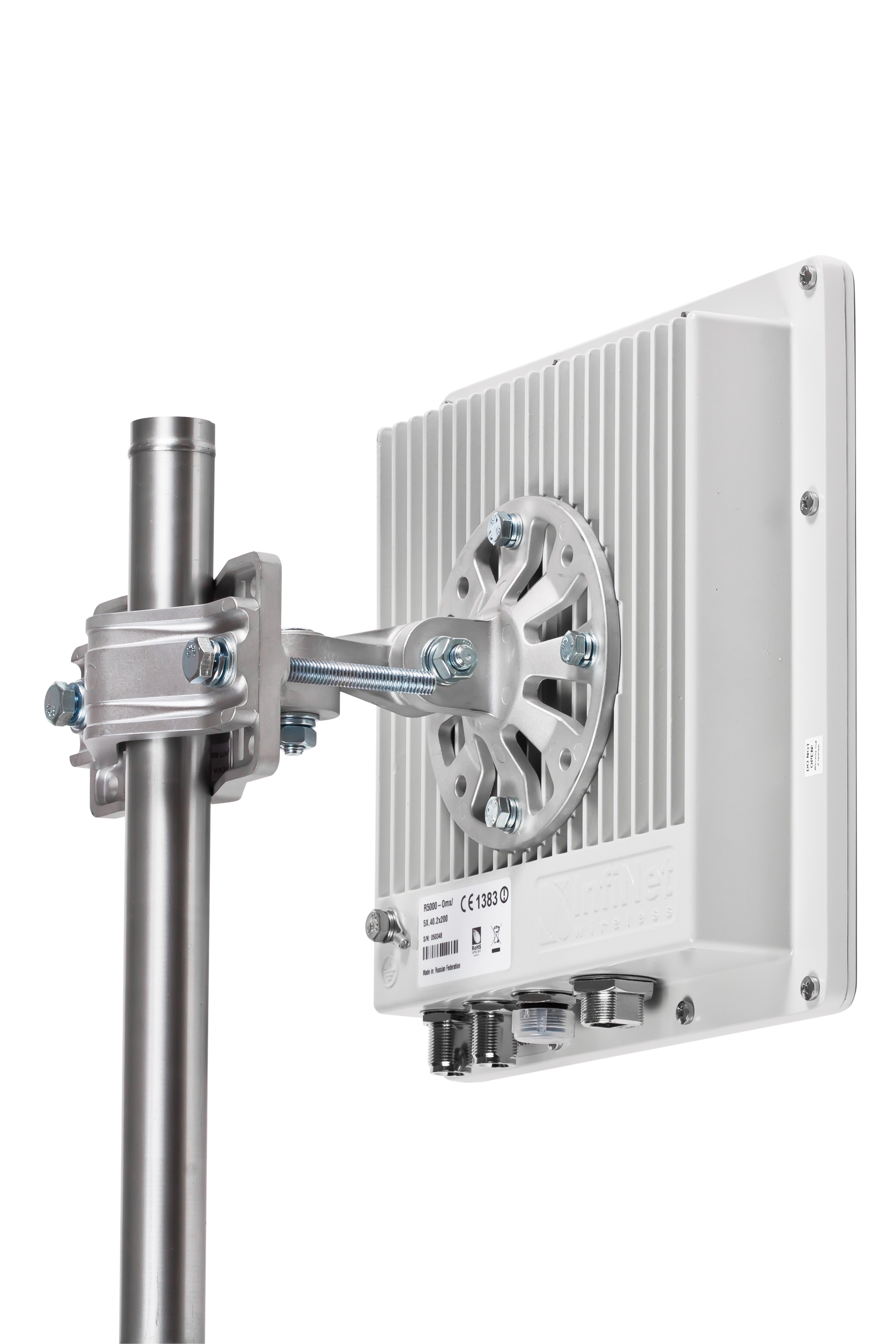
Pole Mounting
The installation of the antenna is performed on a special facility called the antenna pole. The pole is used for strong antenna tightening at the installation site. Poles might differ depending on the installation requirements.
Poles with Stretching
Usually this kind of poles are used when installing antennas on a flat surface and allow the installer to raise the antenna at a significant height for providing optimal conditions for the signal propagation.
Wall Mounting
This kind of mounting is used when there is no need to elevate the antenna above the rooftop and it is possible to mount the antenna on a wall. This installation is significantly simpler than the implementation with poles.
Mostly it is used for subscriber side deployments.
Pole Requirements
Easy access and sufficient mechanical durability of the pole should provide quick and reliable fastening in conditions of high wind loads. The poles should have a round profile for easing the azimuth adjustment. The typical pole diameter is 30 to 85 mm.