Successfully pass the free certification exam at IW Academy and become an Infinet Certified Engineer.
Octopus SDR
Infnet’s latest SDR platform has been designed based on a Software-Defined Radio technology aimed at increasing link performance several-fold. Quanta 5 / Quanta 6 addressing challenges such as limited spectrum availability, growing interference challenges and demands for yet more capacity. Due to Octopus SDR platform Quanta 5 / Quanta 6 allow to bring new PHY, MAC and upper layer features via a firmware upgrade even for the units operating in the field.
Wireless device
An integrated wireless device contains the radio and networking electronics. Implemented in a robust all-weather metal enclosure, this equipment can be used to create point-to-point wireless links at distances in excess of 200 km (depending on country regulations, antenna types, interference, terrain, climate zones, etc.). There are several possible version of Quanta 5 / Quanta 6 solution enclosures:
Quanta 5
- with integrated antenna 28 dBi;
- with integrated antenna 25 dBi;
- with integrated antenna 23 dBi;
- with integrated antenna 18 dBi;
- with two N-type ports for an external antenna.
Quanta 6
- with integrated antenna 28 dBi;
- with integrated antenna 25 dBi;
- with integrated antenna 18 dBi;
- with two N-type ports for an external antenna.
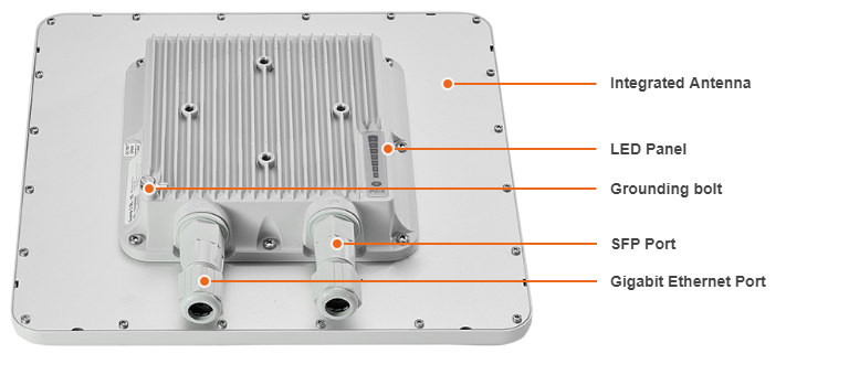
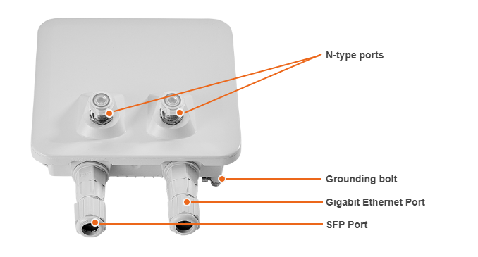
Grounding bolt
For grounding the ODU to the supporting structure.
Interfaces
NOTE
Units with combo port, Ethernet and SFP, have the part number ending with “2”, e.g. Q5-E/08602. If the part number ends with a “0” or “1”, the device has only a Gigabit Ethernet port.
Devices with an integrated 18 dBi antenna only have a Gigabit Ethernet port.
| Interface | Description |
|---|---|
| Gigabit Ethernet | RJ45 socket for connecting to power supply and data transmission. The network connection to the wireless device is made via a 1000BaseT (Gigabit) Ethernet connection. Power is provided to the device over the 1000BaseT Ethernet connection using a standard IEEE 802.3at passive PoE power supply. |
| SFP | External optical Gigabit port for plugging of the optical SFP transceiver module. |
NOTE
Only one port can be used for data transmission at a time. Please note, the SFP port has priority in case both ports are enabled.
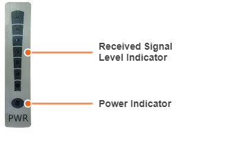
LED Panel
The "POWER" indicator has three possible colors:
- Red light - the device is connected to the electricity mains,
- Yellow light - a wired connection with a speed of 10/100 Mbps
- Green light - a wired connection with a speed of 1000 Mbps.
Other indicators are used to perform coarse antenna alignment. The more indicators are on, the better wireless connection is established. The blinking indicator means an intermediate state.
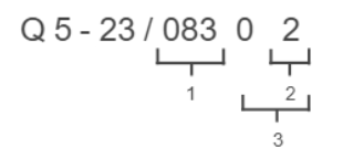
Part number description

Structure items are described below
| Item | Description |
|---|---|
| 1 | Product family name:
|
| 2 | Frequency range:
|
| 3 | Antenna gain:
|
| 4 | Additional options:
|
NOTE
Previously, device part numbers contained decimal number with the following structure:
- Hardware version.
- Options:
- 0 - models with GigabitEthernet port and supporting 40 MHz channel width;
- 1 - models with GigabitEthernet port and supporting 50 and 56 MHz channel widths;
- 2 - models with Combo port GigabitEthernet/SFP and supporting 50 and 56 MHz channel widths.
Firmware version: