Successfully pass the free certification exam at IW Academy and become an Infinet Certified Engineer.
In the "Link Settings" section you can configure the parameters for the Radio interface, for the Pseudo Radio interface and for the Join function:
The "Link Setting" section is consist from the following subsections:
"rf5.0" subsection
This subsection is used for:
Radio link settings
Radio link settings depends from the installed firmware version ("MINT" or "TDMA"). In the "MINT" version Polling technology is used (marker access), in the "TDMA" - TDMA technology (time division access).
NOTE
For more detailed information about TDMA and Polling technologies, their benefits and applications please refer to the document "Application features of TDMA and Polling" - White paper via http://infinetwireless.com/products/materials#white-papers (free registration is required).
Radio link settings in the marker access networks (MINT firmware) allows using two modes of access to the environment:
- Marker access mode - Polling enabled.
- CSMA-CA mode (Carrier-sense multiple access with collision avoidance) - Polling disabled.
The marker access mode (Polling technology) can be enabled on the Master node.
Radio link configuration in networks with time division (TDMA technology) involves setting parameters related to the frame duration and the uplink/downlink ratio.
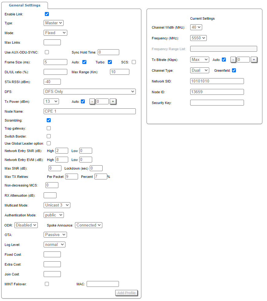
"rf5.0" subsection is divided in two zones:
- The panel that describes global link settings, in the left side of the page
- The panel that describes the radio channel settings which are currently in use, in the right side of the page.
| Parameter | Description |
|---|---|
| General Settings | |
| Enable link |
|
| Type |
|
Polling (Master, MINT firmware only) |
|
MultiBS (Slave) |
|
VBR (Slave) |
|
Radar Detection (Slave) |
|
Max Links (Master) |
|
Use AUX-ODU-SYNC (Master, TDMA firmware only) |
NOTE Information about AUX-ODU-SYNC connection is described in the section "Connection to the synchronization unit". |
Sync Hold Time (Master, TDMA firmware only) |
|
Frame Size (Master, TDMA firmware only) |
|
Auto (Master, TDMA firmware only) |
|
Turbo (Master, TDMA firmware only) |
|
SCS (Master, TDMA firmware only) |
|
DL/UL ratio (%) (Master, TDMA firmware only) |
|
Max Distance (Km) (Master, TDMA firmware only) |
|
STA RSSI (dBm) (Master) |
|
DFS (Master) |
CAUTION Please note that, in some countries, switching “DFS off” and/or failing to detect public service radar signals are against the regulations and may result in legal action. |
| Tx Power |
|
| Node Name |
|
| Scrambling |
|
| Trap gateway |
|
| Switch border |
|
| Use Global Leader option |
|
| Network Entry SNR (dB) |
|
| Network Entry EVM (dB) |
|
| Max SNR (dB) | Limits the maximum signal level, preventing devices connection. If the SNR level of an already connected neighbor is exceeded, the connection will be terminated.
|
| Max TX Retries |
|
| Non-decreasing MCS |
|
| RX Attenuation |
|
Multicast Mode (Master) |
Transformation to "Unicast" requires memory data copying that increases CPU load. Besides, the use of "Unicast" streams increases the volume of transmitted traffic proportional to the number of subscribers and reduces the sector available throughput. NOTE "Unicast 3" mode is set by default. NOTE Transformation of "Multicast" to "Unicast" via CLI is described in the section "mint command". |
| Authentication Mode |
|
| ODR | Activate routing using the ODR protocol. The following modes are available:
The main advantage of ODR protocol is a network throughput efficient use. Part of the link throughput is usually used by the routing protocol to transmit service information, this part can be released by ODR using. The ODR protocol transmits the hosts IP prefixes using the MINT protocol at the data link layer. The ODR protocol can only be used in networks with star topology, where all nodes are connected to the central node only. An example of such a network is a point-to-multipoint topology, where each subscriber is connected only to a base station. The "Spoke Announce" parameter allows to select the type of notifications sent by the spoke node to the hub:
|
| OTA | Automatic updates in the MINT domain may be configured in the following modes:
|
| Log Level |
|
| Fixed Cost |
|
| Extra Cost |
|
| Join Cost |
|
| MINT Failover |
|
| Current Settings | |
| Channel Width |
|
| Frequency |
|
| Frequency Range List |
|
| Tx Bitrate |
|
| Channel Type |
|
| Greenfield |
|
| Network SID |
|
| Node ID |
|
| Security Key |
|
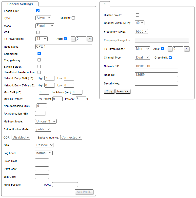
On each radio profile, the following options are available (for the Slave unit only):
- "Disable profile" check box disable a radio profile
- Add a new radio profile by clicking the «Add Profile» button
- Copy the radio profile values to a new radio profile by clicking the «Copy» button
- Remove the radio profile by clicking the «Remove» button.
It is suitable to configure radio profiles for the Slave units (with complete radio parameters of each BS) in a PtMP deployment when the CPEs can be linked to more than one BS either in fixed, nomadic or mobile situations, for the redundancy purpose (different profile for each BS). When the CPE tries to establish a wireless connection, it chooses the BS with the best link quality (determined by the RSSI, SNR, bitrate, number of errors, number of retries, etc.). If the connected BS is down, the CPE retries to connect to it once and in case of failure, it looks for a new BS to connect, if the SNR allows it and if one of its radio profiles matches with the radio parameters of the new BS (in case of "MultiBS" option disabled)
Software with TDMA technology support ensure more faster base station search. When the CPE tries to establish a wireless connection, it chooses the BS with the best link quality (determined by the RSSI, SNR, bitrate, number of errors, number of retries, etc.). If the connected BS is down, the CPE doesn't try reconnect, but evaluate the signal parameters of all available base stations sectors.
The frequency roaming feature (which is enabled in the default configuration) allows the CPE with auto frequency set (roaming enable) to:
- Automatically switch from the main BS (roaming leader) to the backup BS (if it is provisioned with the radio profiles of both BSs)
- Automatically switch between different BSs while the CPE is moving (if it is provisioned with the radio profiles of the BSs)
- Automatically switch to the new frequency of the BS in case the current frequency was changed by the BS.
Data traffic is not interrupted during frequency roaming.
NOTE
In case of first TDMA firmware installation (instead of polling), the system automatically will starts the Master TDMA mode, which works in the Master Polling mode (mint pollstart) with the parameters "win = 5, dist = 70, dlp = 50, rssi = -20". These settings are not optimal for most networks, but allow to recover quickly network functioning at the first start. All other devices will be launched in the Slave TDMA mode. It gives the opportunity to transfer already operating network to TDMA. At first it is necessary to update firmware on Slave devices and reboot them. Then to update the firmware on the base station.
NOTE
Read the information in the section "Apply, Try and Preview buttons for the configuration" in order to find out the output of the «Apply», «Test», «Preview» and «Show changes» buttons for the new configuration performed.
Frequency limitation
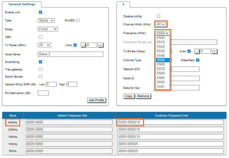
The licensed frequencies range per each bandwidth is displayed in the "rf5.0" subsection, in “Default Frequency Grid” fields. Changes to these default values can be performed in the “Customer Frequency Grid” fields; you can:
- Limit the licensed frequencies range per each Channel width (see the screenshot below)
- Change the center frequency step (for example: 4915-5945/5 means that the step between the center frequencies from 4915 GHz and 5945 GHz is 5MHz).
The changes performed in “Customer Frequency Grid” will be available in the “Frequency” drop down list from the radio profiles and in DFS page in “Frequency grid” field.
Setting channel type mode
When Channel Type is set to “Single”, then Tx and/or Rx of Chain #1 (for horizontal polarization antenna) can be deactivated:
- "Chain #0" is connected to the port of the vertical polarized integrated antenna
- "Chain #1" is connected to the port of the horizontal polarized integrated antenna
If the "Single" mode is selected when, then "Chain #1" column (horizontal polarization) can be disabled for transmission (TX) and / or reception (RX):
NOTE
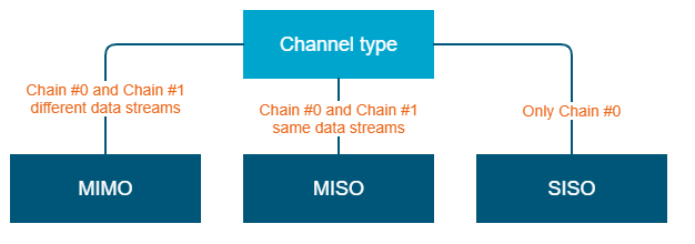
MIMO, MISO and SISO are defined from the perspective of the data sent by the local unit (not considering the number of physical antennas used for tx and rx like in the classical definition). Therefore, these represent local configuration options. For example, one stream of data can be sent by one chain (1 antenna) corresponding to SISO or the same stream can be sent by both chains (2 antennas) corresponding to MISO.
Settings for "MIMO" mode
Different data streams are transmitted over "Chain #0" and "Chain #1". MIMO uses multiple antennas at both the transmitter and receiver side to improve communication performance and data is sent on both the horizontal and vertical polarizations (data is space-time coded - spatial multiplexing, to improve the reliability of data transmission):
| Channel Type | Dual | |
|---|---|---|
| Radio Chain | #0 | #1 |
| Rx |
Activated
|
Activated
|
| Tx |
Activated
|
Activated
|
Settings for "MISO" mode
The same data streams are transmitted over "Chain #0" and "Chain #1", lowering the performance of the link, but enhancing the ability to transmit data in case of interference or obstacles in transmission path (a special mode of operation of MIMO devices used in NLOS conditions or in a noisy RF environment):
| Channel Type | Single | |
|---|---|---|
| Radio Chain | #0 | #1 |
| Rx |
Activated
|
Activated
|
| Tx |
Activated
|
Activated
|
Settings for "SISO" mode
The data streams are transmitted over Chain #0 (corresponding to vertical polarization) only, lowering the performance of the link, but increasing the link distance (transmitter operates with one antenna as does the receiver; there is no diversity and no additional processing for recomposing the Rx signal):
| Channel Type | Single | |
|---|---|---|
| Radio Chain | #0 | #1 |
| Rx |
Activated
|
Deactivated
|
| Tx |
Activated
|
Deactivated
|
The picture below summarizes the link establishment between two units that are configured in different operational modes. As it can be noticed, only the combination MIMO – SISO is not functional.
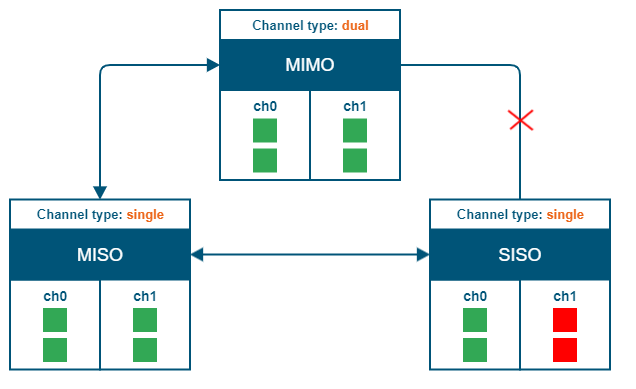
"prf" subsection
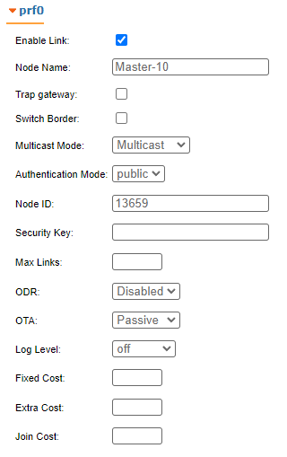
In the "prf" subsection, you can configure the pseudo-RF link as a MINT network node. The "prf" subsection is available for configurations only after at least one pseudo-RF interface has been created in "Network Settings" section. Pseudo-RF virtual interface is used to provide MINT-over-Ethernet. Every BS or CPE supports PRF interfaces. All parameters available in "prf" subsection are explained in "rf5.0" subsection above:
"Join" subsection
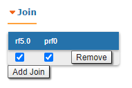
In the "Join" subsection, you can link two or more radio/pseudo-RF interfaces of one unit into one MINT domain. Each of these interfaces may act as an independent MINT network node. The "Join" subsection is available for configurations only after at least one pseudo-RF interface has been created in "Network Settings" section.
In order to join the interfaces, simply enable the check boxes of the corresponding interfaces, as shown in the screenshot below:
