Successfully pass the free certification exam at IW Academy and become an Infinet Certified Engineer.
Reqiered tools
Screwdriwer set.
Pliers / pipe wrench.
Wrench set.
Additional equipment
- GPS receiver.
- High magnification binoculars.
CAUTION
Before mounting the equipment in an outdoor environment, please make sure that:
- You acknowledge the regulations imposed by the Regulatory Authority for Communications in your country for the radio spectrum to be used.
- You chose known locations for the installation of the links; although InfiNet Wireless devices can also operate in Near-LoS or Non-LoS conditions, to achieve the best performance, it's highly recommended to install the link in locations where Clear-Line-of-Site and clear channels are available.
- You performed link planning using the InfiPLANNER tool (https://infiplanner.infinetwireless.com) to determine the link path profiles, radio equipment placement requirements, etc.
- You met requirements described in the section "Planning considerations" - > "Wireless device placement".
Installation Procedure
In case of device with external antenna, mount and connect an external antenna to the device in accordance with the following recommendations:
Mount the antenna according to manufacturer’s instructions;
Connect the ODU V and H N-type interfaces to the antenna with RF coaxial cables and with appropriate connectors. Use cables not longer than 1 m (3.3ft). Tighten the N-type connectors to a torque setting of 1.7 Nm (1.3 lb ft);
Form drip loops near the cable ends at the ODU’s side so that water doesn’t creep towards the ODU connectors;
Weatherproof the N-type connectors (when antenna alignment is complete) using PVC tape and self-amalgamating rubber tape;
Weatherproof the antenna connectors in the same way (unless the antenna manufacturer specifies a different method);
Fix the antenna cables to the supporting structure using site approved methods. Ensure that no undue strain is placed on the ODU or antenna connectors. Ensure that the cables do not flap in the wind, as flapping cables are prone to damage and induce unwanted vibrations in the supporting structure.
CAUTION
In order to prevent device damage make sure that antenna is connected to both N-type connectors with serviceable RF cables before switching on
- Install ODU connector facing down using the mounting kit. Do not tighten the fasteners to the end until the alignment is completed.
- Connect the Cat5e FTP cable with the cable gland to ODU.
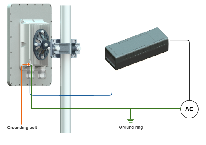
- Perform ODU grounding.
- Lay the Cat5e FTP cable from ODU to the power supply.
Connect the Cat5e FTP cable with a shielded connector covered by a cap to the "OUT" port of the power supply, having previously touched the power supply connector case with FTP cable connector case.
CAUTION
The power supply must not operate near a direct heat source, near water or in an environment with high humidity. The cables must be connected in such a way to prevent water flow to the power supply connectors.
- Perform the power supply grounding.
- Connect the laptop using Cat5e FTP cable to the power supply "IN" port.
Connect the power cord to the power supply and then to the power circuit.
CAUTION
Use mains supply cords that adhere to safety regulations of the country where the equipment is getting deployed.
Make sure a small loop (at least 10 cable diameters) is provided before the Cat5e FTP cable enter into the building.
CAUTION
This equipment is a source of electromagnetic energy and exposes public and personnel to RF electromagnetic emission. Guaranteed safe distance to human body during operation is 20cm (7.9in) and greater.
CAUTION

Surface of device may become hot during operation, contact may cause burn. Allow to cool before handling.
CAUTION
Please note that the pressure equalization system in Infinet devices is performed via gas exchange through a cable gland and Ethernet cable jacket with a dry room where the power supply is installed. In order to avoid ODU failure due to moisture entering the device, for example, during the pressure drop during the rain, the cable gland assembly requirements should be met and there are should be no cracks in the Ethernet cable jacket.
In addition, you should avoid the Ethernet cable bending near the ODU and pinching with clamps, that can bring to the pressure equalization system fault between the internal volume of the sealed ODU and the external environment during a sudden air temperature change. This may lead to the leakage and device failures.