Successfully pass the free certification exam at IW Academy and become an Infinet Certified Engineer.
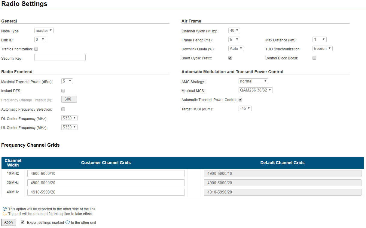
The radio page is divided in two sections:
- "Radio Settings" - allows you to configure general radio parameters and features:
- General
- Air Frame
- Radio Frontend
- Automatic Modulation and Transmit Power Control
- "Frequency Channel Grids" - specifies the default and custom frequency domains for each bandwidth (10, 20, 40 MHz).
Radio Settings
The following radio parameters can be configured under the "Radio Settings" section:
| Radio parameter | Description |
|---|---|
| General | |
| Node Type |
|
| Link ID |
|
| Traffic Prioritization |
NOTE If "VLAN-based Switching" is enabled and prioritization is configured for "Default VLAN", tags priorities will be autlomatically assigned to the frames when they are sent over the radio interface. In this case port modes must differ from "Untagged" and "Off". |
| Security Key |
|
| Air Frame | |
| Channel Width (MHz) |
|
| Frame period (ms) |
|
Downlink Quota (%) |
|
| Short Cyclic Prefix |
|
| Max Distance (km) |
|
| TDD Synchronization |
NOTE To ensure two Masters synchronization from the synchronization source:
|
| Control Block Boost |
|
| Radio Frontend | |
Downlink Center Frequency, MHz (5 GHz units) |
|
Uplink Center Frequency, MHz (5 GHz units) |
|
Center Frequency, MHz (6 GHz units) |
|
| Maximal Transmit Power (dBm) |
|
| Instant DFS |
NOTE The "Instant DFS" option is only available for the InfiLINK XG family 5 GHz devices. |
| Automatic Frequency Change Timeout (s) |
|
| Automatic Frequency Selection |
NOTE The "Automatic Frequency Selection" option is NOT available for the InfiLINK XG 1000 family devices. |
| Automatic Modulation and Transmit Power Control | |
| AMC Strategy |
|
| Maximal MCS |
|
| Automatic Transmit Power Control |
|
| Target RSSI (dBm) | The RSSI target value:
|
NOTE
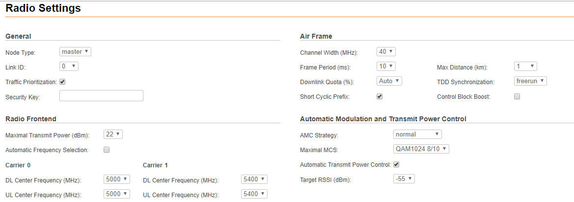
For the InfiLINK XG 1000 family models the following parameters can be configured for both radio modules:
- DL Center Frequency
- UL Center Frequency.
The minimum required guard interval between center frequencies of "Carrier 0" (the first radio module) and "Carrier 1" (the second radio module) should be:
- 20 MHz - for 10 MHz channel width
- 40 MHz - for 20 MHz channel width
- 80 MHz - for 40 MHz channel width.
CAUTION
Setting the source of synchronization takes effect only for the Master unit.
CAUTION
Make sure that the built-in GNSS receiver is set up before enabling the “gnss” option (use “gps” command to check the status - it is recommended to use values of “HDOP” parameter up to 1.5 for reliable global timing synchronization).
CAUTION
Please note that the following settings must be equal for "master" and "slave" unit to establish the radio link:
- Center Frequency
- Channel Width
- Frame Period
- Short Cyclic Prefix
- Link ID
NOTE
In order to export and apply option markedto the other side of the link check the box "Export settings markedto the other unit" and click the "Apply" button.
NOTE
Safety apply settings mode is activated by default on devices. Mode principle of work is detailed described in the document "Safety apply settings in InfiLINK XG / InfiLINK XG 1000".
Frequency Channel Grid
The licensed frequencies range per each bandwidth is displayed in the “Default Channel Grids” fields:
- For 10 MHz bandwidth: value range between 6295...6405 MHz in increments of 10 MHz
- For 20 MHz bandwidth: value range between 6300...6400 MHz in increments of 20 MHz
- For 40 MHz bandwidth: value range between 6300...6400 MHz in increments of 20 MHz
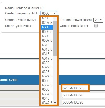
Changes to these default values can be performed in the "Customer Channel Grid" fields, where you can:
- Limit the licensed frequencies range per each bandwidth
- Change the center frequency step (for example, 6295-6405/2.5 means that the step between the center frequencies from 6295 MHz and 6405 MHz is 2.5 MHz):
The step must be >= 1 MHz and the frequencies range (determined by the license) cannot be exceeded.


