Successfully pass the free certification exam at IW Academy and become an Infinet Certified Engineer.
CAUTION
Configurations from the scenarios below are examples that demonstrate the potential capabilities of the InfiNet Wireless devices. The configurations may vary depending on the model and firmware version. We do not recommend copying this solutions to the hardware without checking.
Description
InfiLINK XG/InfiLINK XG 1000 devices do not have software functionality for redundant links. However, you can create two redundant links on them with using third-party devices based on public technologies.
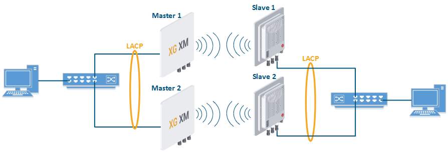
The simplest scheme will be the organization of two links established at the 2 level of OSI via two InfiLINK XG/InfiLINK XG 1000 devices. LACP protocol excludes loops and allows to increase throughput.
NOTE
The wireless devices management and monitoring are possible in the described configuration using the second Ethernet port. In order to retain the ability to manage devices using a single wired port, use the configuration method described in the "Management in LAG" section.
Unfortunately, in this case, the use of one frequency for two pairs of devices is not desirable.
Configuration Example
Configure Master 1 and Slave 1 as the main link.
Master 1xg -type master xg -tdd-sync-src freerun xg -cell-id 1 xg -channel-width 40 xg -freq-dl 5000 xg -freq-ul 5000 xg -short-cp 1 xg -freq-auto 0 xg -max-distance 1 xg -sframelen 5 xg -tdd-profile-auto-switching 1 xg -txpwr 0 xg -ctrl-block-boost 1 xg -atpc-master-enable 1 xg -atpc-target-rssi -55 xg -atpc-rssi-threshold 1
Slave 1xg -type slave xg -tdd-sync-src freerun xg -cell-id 1 xg -channel-width 40 xg -freq-dl 5000 xg -freq-ul 5000 xg -short-cp 1 xg -freq-auto 0 xg -max-distance 1 xg -sframelen 5 xg -tdd-profile-auto-switching 1 xg -txpwr 0 xg -ctrl-block-boost 1 xg -atpc-master-enable 1 xg -atpc-target-rssi -55 xg -atpc-rssi-threshold 1
Configure Master 2 and SLave 2 as a backup link.
Master 2xg -type master xg -tdd-sync-src freerun xg -cell-id 2 xg -channel-width 40 xg -freq-dl 5100 xg -freq-ul 5100 xg -short-cp 1 xg -freq-auto 0 xg -max-distance 1 xg -sframelen 5 xg -tdd-profile-auto-switching 1 xg -txpwr 0 xg -ctrl-block-boost 1 xg -atpc-master-enable 1 xg -atpc-target-rssi -55 xg -atpc-rssi-threshold 1
Slave 2xg -type slave xg -tdd-sync-src freerun xg -cell-id 2 xg -channel-width 40 xg -freq-dl 5100 xg -freq-ul 5100 xg -short-cp 1 xg -freq-auto 0 xg -max-distance 1 xg -sframelen 5 xg -tdd-profile-auto-switching 1 xg -txpwr 0 xg -ctrl-block-boost 1 xg -atpc-master-enable 1 xg -atpc-target-rssi -55 xg -atpc-rssi-threshold 1
- Configure LACP (not included in the example).
Management in LAG
NOTE
This scheme can be implemented only when using InfiMUX switches, the configuration can not be applied for third-party switches.
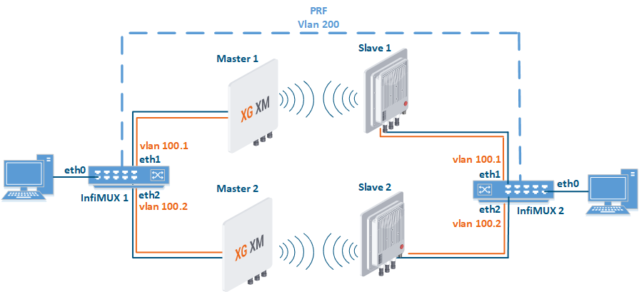
- VLAN 100 is allocated for device management.
- VLAN 200 is allocated for the traffic transmission. All data traffic will be encapsulated in PRF (including VLAN 100) and forwarded unchanged in VLAN 200 from InfiMUX 1 to InfiMUX 2. VLAN 200 is used only on the network part between InfiMUX 1 and InfiMUX 2, its use in the rest of the network is not prohibited.
- To prevent a loop VLAN 100 transmission over the radio must be disabled.
InfiMUX configuration
Step 1: To transmit VLAN 100, create the vlan100.1 interface over the eth1 physical interface (toward the device of the first radio link), the vlan100.2 interface over the eth2 physical interface (toward the device of the second radio link).
ifc eth1  info "Link 1"
ifc eth2  info "Link 2"
ifc vlan100.1 up
ifc vlan100.1 vlan 100 parent eth1
ifc vlan100.2 up
ifc vlan100.2 vlan 100 parent eth2
Step 2: To transmit VLAN 200, create the vlan200.1 interface over the eth1 physical interface, the vlan200.2 interface over the eth2 physical interface.
ifc vlan200.1 up
ifc vlan200.1 vlan 200 parent eth1
ifc vlan200.2 up
ifc vlan200.2 vlan 200 parent eth2
Step 3: Join the vlan200.1 and vlan200.2 interfaces using the LACP protocol.
ifc lag0  up
lag 0 mode fast balance-pp port vlan200.1 vlan200.2
Step 4: Create the PRF interface over the lag0 parent interface.
ifc prf0  up
prf 0 parent lag0
mint prf0 -name "MUX-1"
mint prf0 -type master
mint prf0 -mode fixed
mint prf0 start
Step 5: Create a switch group 100, add the eth0 interface, the prf interface to transfer data traffic, and the vlan100.1 and vlan100.2 interfaces to manage radio devices. Create an svi100 interface to manage the InfiMUX switch, assign it an IP-address allocated for management.
switch group 100 add 1 eth0 prf0 vlan100.1 vlan100.2
switch group 100 start
ifc svi100 up
ifc svi100 192.168.100.1/24
svi 100 group 100
- Step 6: Configure the second InfiMUX switch in the same way.
Wireless devices configuration
- Step 1: Set wireless links between Master 1 - Slave 1 and Master 2 - Slave 2 devices.
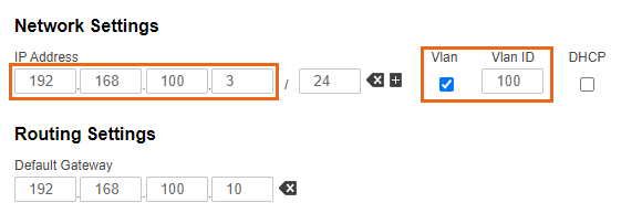
Step 2: At the "Network access" set the IP address allocated for the device, associate VLAN 100 with it.
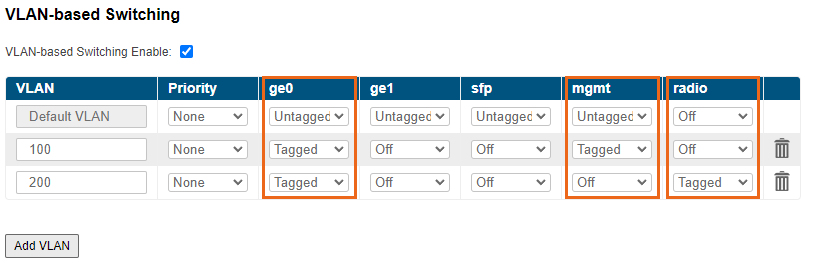
- Step 3: In the "Switch" section, allow VLAN 200 transmission between the ge0 and radio interfaces. Allow management in VLAN 100 for interface ge0. Note that transmissionover the radion of VLAN 100 and the default VLAN used for local configuration must be disabled. Management in VLAN 200 must be disabled also.
- Step 4: Configure all radio devices in the same way.