Successfully pass the free certification exam at IW Academy and become an Infinet Certified Engineer.
For this example, we have two InfiNet Wireless R5000 units with the default factory configuration.
- Step 1
In order to access each of the units, we have to make sure that there is network connectivity between the PC used for the configurations and the units on their default Ethernet IP address which is 10.10.20.1/24.
- Step 2
Connect to the first unit using a Web browser and type any username and any password in the corresponding fields. Let’s use in this example “test” for both username and password. After the authentication, a warning message pops up and requests us to change these initial authentication credentials:

- Step 3
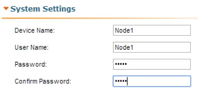
In order to change the initial credentials, we have to go to "Basic Settings" → "System Settings" and fill in the “User Name” and “Password” fields with the permanent authentication credentials. Let’s use in this example “Node1” user name and “Infi1” password for the first unit and “Node2” user name and “Infi2” password for the second unit.
In the same section, we set the “Device Name” parameter for each unit. Let’s name in this example “Node1” the first unit and “Node2” the second unit:
- Step 4
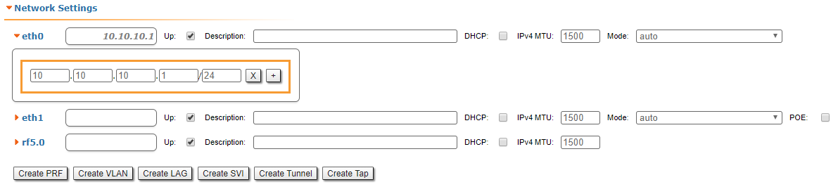
In "Basic Settings" → "Network Settings" section, we can change the default IP address of the Ethernet interface. Let’s add the IP 10.10.0.1/24 for the first unit and the IP 10.10.10.2/24 for the second unit:
- Step 5
In order to establish a wireless link between the two units, we have to set one of them as Master. By default, both units are configured as Slave.
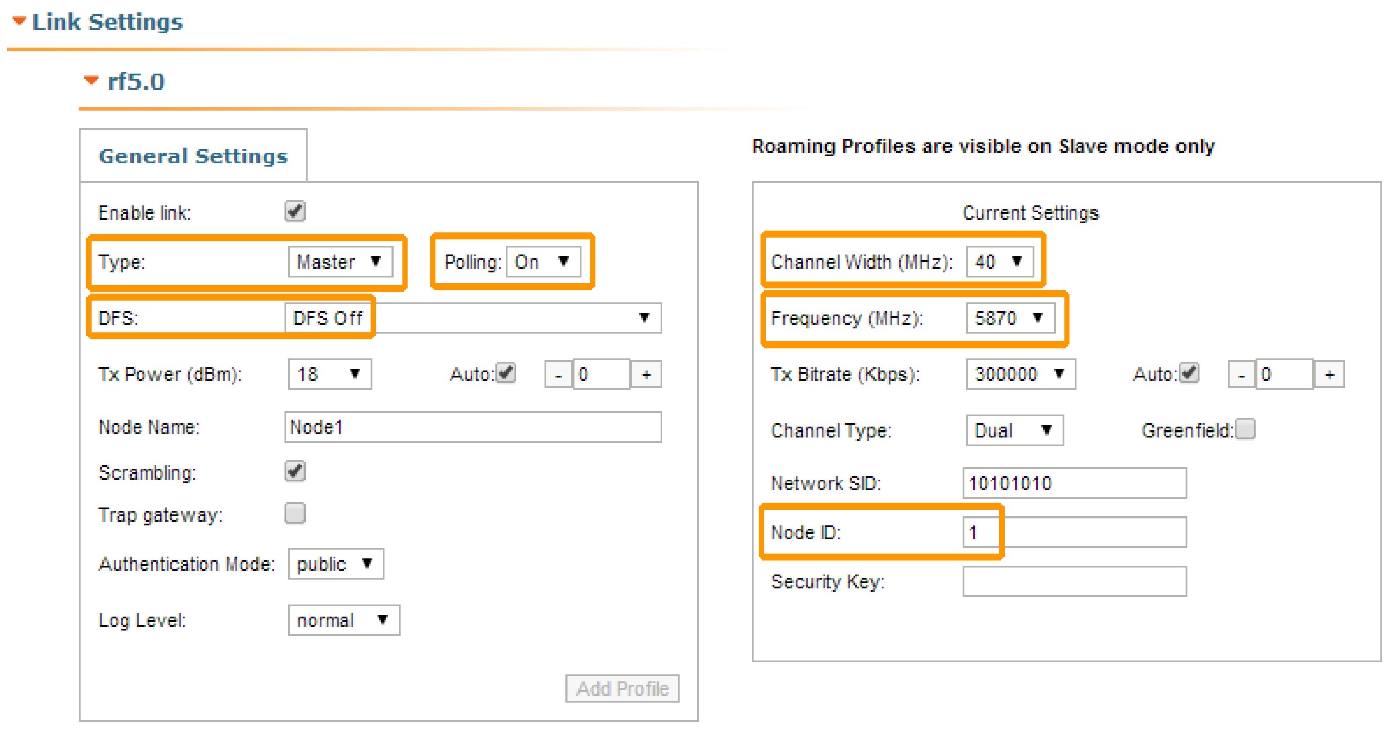
In "Basic Settings" → "Link Settings" section let’s configure the following radio parameters for the first unit:
- Type: Master
- Polling: On
- DFS: Off
- Node ID: 1
- Channel width: 40 MHz
- Frequency: 5870 MHz
- Step 6
Now we can save all settings performed in "Basic Settings" menu by clicking the «Apply» button at the bottom of the page.
- Step 7
We have now to connect to the second unit to its default IP address and to perform the configuration below:
- In "System Settings" section
- Device Name: Node2
- User Name: Node2
- Password: Infi2
- In "Network Settings" section
eth0 IP address: 10.10.10.2/24
In "Link Settings" section
- Type: Slave
- Node ID: 2
- Channel width: 40 MHz
- Frequency: 5870 MHz
We have to save all settings performed in "Basic Settings" menu by clicking the «Apply» button at the bottom of the page.
- Step 8
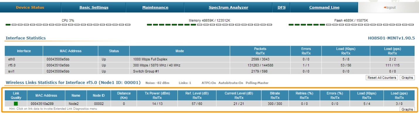
We connect now back to the first unit at the assigned IP, and go to "Device Status" menu in order to check the link establishment between our two units and all real-time parameters provided by Web interface:
- Step 9
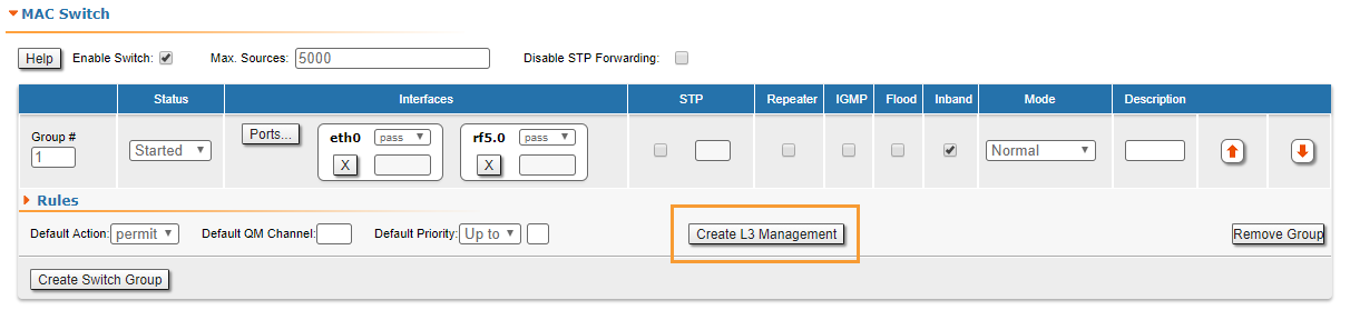
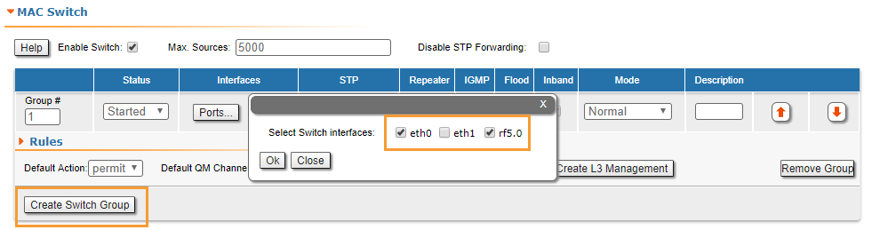
R5000 family devices allows to control data transfer using switch groups concept. We have to create a switch group 1, which will pass tagged and untagged traffic (this group is created by default). In the "MAC-Switch" section create a switch group 1 by clicking the "Create a switch group" button, add the Ethernet and Radio interfaces by clicking the "Ports" button.
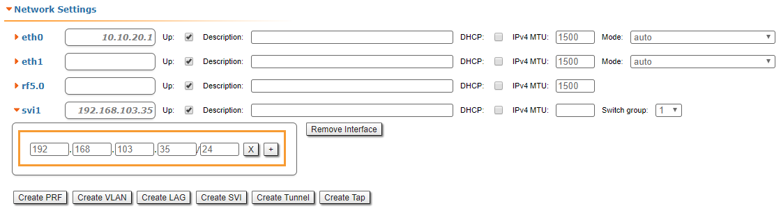
- Step 10 (optional)
To ensure device management not only via the wired segment, but also by radio, let's create an svi interface. Click the "Create L3 Management" button, and assign an IP address selected for device management. For more information about remote management, see the "Remote management of the R5000 units" article.