Successfully pass the free certification exam at IW Academy and become an Infinet Certified Engineer.
Abbreviations and definitions
The following abbreviations are used in this document:
- ARQ - Automatic Repeat reQuest
- BS - Base Station
- CPE - Customer Premises Equipment
- CSMA/CA - Carrier Sense Multiple Access with Collision Avoidance
- MIMO - Multiple Input Multiple Output
- NLOS - Non-Line of Sight
- PtMP - Point to MultiPoint
- SLA – Service Level Agreement
- TDMA - Time Division Multiple Access
- VoIP - Voice over IP
- WBA - Wireless Broadband Access
The following definitions are used in this document:
- Downlink – Data flow from BS to CPE
- Uplink – Data flow from CPE to BS
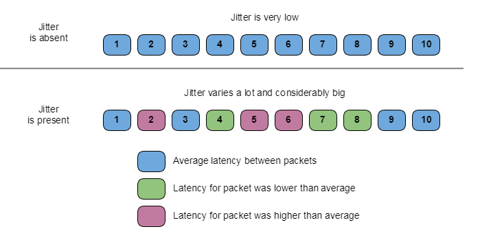
- Jitter – Packet delay variation
- Retry – Repeated packet transmission
- Time frame – Amount of time allocated for Uplink and Downlink transmissions
- Triple play – Telecommunication term for the provisioning of bandwidth-intensive services: broadband Internet service, television and latency-sensitive telephony
- Subslot – Time frame divides into Uplink and Downlink slots. In its turn, each slot divides into subslots. Each subslot intended for different devices. The purpose of subslots – data transfer from several CPEs within single Uplink slot in PtMP topology
Introduction
The purpose of this document is to present information about the features and applicability of the TDMA and Polling technologies for MIMO units of the R5000 product family.
All MIMO devices of the R5000 product family could be used with Polling technology (by default), or with TDMA technology. Polling firmware version described as “MINT”, TDMA firmware as “TDMA”. Both software versions are available on the official InfiNet Wireless FTP server: https://ftp.infinet.ru/pub/Firmware/.
Firmware upgrade fully replaces previous firmware, configuration kept with no modifications after upgrade. Upgrade could be done during any free from service provision technological cycle with short-time wireless network link interruption (device reboot is required for firmware upgrade).
NOTE
Software upgrade process from firmware “MINT” to “TDMA” is described in details here: How to upgrade from MINT to TDMA.
Necessary description of 802.11x protocol features
Functionality of R5000 product family is based on 802.11х standards.
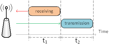
Half-duplex transmission
All MIMO devices of R5000 product family have only the one radio module, therefore they cannot transmit and receive data simultaneously. In other words, they work in half-duplex scheme.
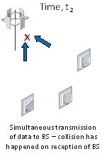
Collisions
Collision on reception in “point-to-multipoint” topology (PtMP) occurs when two subscriber terminals (CPE) simultaneously transmit data to the base station (BS).
Immediately after collision, both subscriber terminals (which have caused collision) have to repeat same data transmission once again. If collisions take place all the time, then the traffic volume decreases significantly, latency between packets increase, packet delay variation (jitter) becomes too big (for proper service operation), real-time services (VoIP, video conferences) exposed distortions.
![]()
Polling technology
Algorithm CSMA/CA
Polling technology uses the algorithm CSMA/CA, described by 802.11x standards set, as the method for media access.
CSMA/CA was created in order to resolve collisions issue, which happened with multiple access in PtMP topologies.
This method implies mandatory medium monitoring before the start of transmission. The reason of medium monitoring is to make sure no other radio is transmitting at the same moment. Therefore, one CPE could start transmission only when all other devices expect to receive data. Moreover, during transmission receiving side sends the mandatory confirmation of received data by special acknowledgement packet (ACK).
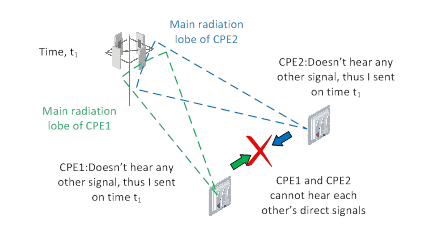
Proper operation of CSMA/CA algorithm requires the important factor accomplishment: all CPEs should be able to listen directly each other’s signals. In case, the radio radiation from some CPEs could not be detected by the other CPEs (for example, narrow beam antennas with high gain in the limited radiation sector were used) – then different subscriber terminals would transmit simultaneously, thus causing collision on BS receiving side.
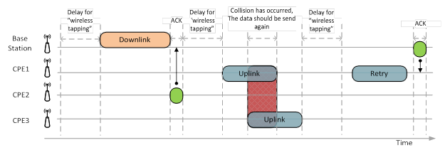
Collision detection due to “wirelesstapping” before the transmission stops working: the air will always be free, excluding time when the BS sends Downlink traffic.
Moreover, the necessity for air “wirelesstapping” introduces additional delay, which could vary randomly within a broad range (especially under the heavy interference), which in turn results in increased jitter. Receiving side will send immediately the special acknowledgement packet (ACK) upon each successful packet reception, therefore transmission completes very fast. In case, the data integrity could not be confirmed by ACK, then whole data packet should send one more time. The process to send the same data again through the wireless link is called Retry.
The advantage of CSMA/CA algorithm is the following: the transmission of some certain size packet requires the same amount of time, which requires for data propagation in the air. Such advantage is applicable for Polling technology too.
Packet sizes varies due to type of traffic is being generated by customers, thus for small packets sizes (Internet data, IP telephony) delay and round trip time would be considerable small too. Consequentially, when traffic with big packet sizes is being transmitted – delays and round trip time increase.
Mixed traffic transmission, when different services and therefore different packet sizes mixed, for example, video and web traffic simultaneously – jitter increases a lot.
It is also worth to mention that delay could be even higher, due to operation of automatic repeat Request (ARQ) mechanism. Latency would increase proportionally in multiples of retries number, cause retransmission data would be send again and again until the data would arrive with successful acknowledgement or explicitly dropped.
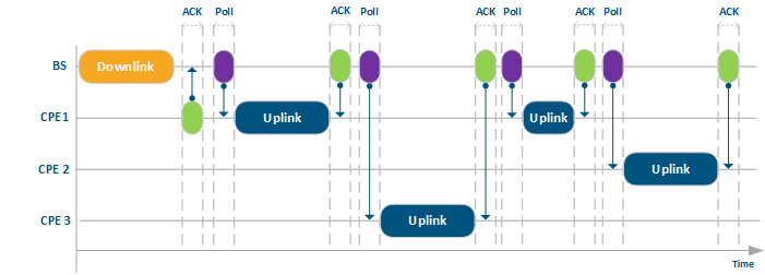
Polling technology operation
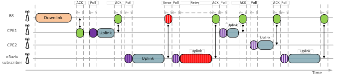
Once of the collision avoidance solutions is Polling – strict control of the transmission from all subscriber terminals from the base station side by using special admission for CPE to start Uplink transmission. BS sends the special service packets “markers” (poll), which admits CPE to start Uplink transmission. The transmission won’t start until the CPE receives “marker” from the BS, which of course leads to latency increase.
The distribution by the BS of special “markers” among the CPE’s normalizes their operation, cause only one subscriber can start transmission after the “marker” receiving. Thus, only one CPE can transmit at certain time, therefore all collisions will be eliminated. It is worth to mention, the whole transmission cycle follows the same process as described above.
Acknowledgement and retries process brings more reliability in general and decreases the amount of lost data. At the same time, such operation could create a problem in PtMP topology, because one “bad” subscriber with a lot of interference increase latency for all subscriber terminals, which don’t have any interference instead and could sent more traffic. In result, total throughput of the base station significantly depends from the existence of such “bad” subscriber terminals.
NOTE
Configuration of units in the marker access networks (Polling technology) should be done in accordance with recommendations from the documentation: Link Settings
TDMA technology
Another way to prevent collisions is to use TDMA technology.
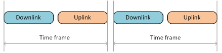
TDMA splits every communication session into two time-frame streams from the unit (for example, from BS to CPE) and, in the backward direction, to the unit. Each time frame has the same size, which is determined by the transmission time (for example, 10 ms), and also depends on the channel band size, modulation scheme and some other parameters.
At regular intervals, according to a certain algorithm, each device receives one allocated time frame to transfer accumulated data. Herein it is guaranteed that transmission would start at the given time and will last only during allowed fixed time. The same considerations applicable for all different data types: service packets, acknowledgement packets, retries (if required).
Each time frame divides into Uplink and Downlink slots according to assigned in configuration.
Unlike of Polling technology, TDMA provides synchronization between the base station and subscriber terminals.
Each device connected to the base station sector, synchronizes its clock in such a way so time on all devices within the same PtMP flows synchronously within the accuracy of microseconds. Hereafter, each communication session starts during fixed duration time intervals (time frames).
Therefore, each subscriber terminal will transmit data only during uplink part of time frame specially allocated by the base station.

TDMA uses continuous byte stream transmission instead of packet transmission used in Polling technology. This is done specially in order to fully utilize limited time devoted for transmission. TDMA byte stream is divided into multiple portions, but these portions are cut according to time size, not by length. Therefore, since total size of time frame is fixed, then in case of insufficient data to fill time frame completely – the unloaded part of time frame would be sent in vain. Usage of shorter time frames size helps to amend such drawback and at the same time decrease latency, however the short time frame size leads to decrease proportion of customer traffic payload within the time frame and decrease of maximum throughput.
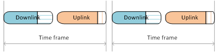
TDMA limitation constitute in the following: the throughput is static for Uplink and Downlink too (when fixed Uplink/Downling ratio set). Therefore, the following statements are right:
In case, the amount of data for transmission exceeds the time frame size – then output queue would increase and the data delivery would require more time.
In case, the amount of data for transmission fails to fill up the time frame size – some amount of wireless link throughput won’t be used. Such situation illustrated at the picture below.
TDMA time frame structure
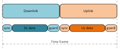
Sync – service information, required to maintain synchronization of the wireless link and ARQ mechanism operations. It has a fixed duration, which depends only on the current channel width. Sync doesn’t depend from the time frame size.
Guard – protective interval to prevent collisions occurrence. The duration of the protective interval depends only on the distance between units (approximately 3 µs for 1 km).
The total volume of the service information (Sync + Guard) more or less is constant for the selected channel width and distance and doesn’t depend on the time frame duration. Therefore, the change of the time frame duration leads only to change of customer payload data size (Downlink Data / Uplink Data).
As you can see in the picture below, with time frame halving (size decreases from 5 ms to 2.5 ms), amount of customer payload data decrease considerably higher (more than two times).
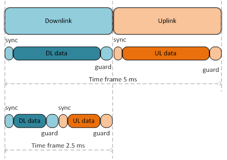
In case of consideration of the same amount of time, payload data would be much less with shorter time frame than with longer. However, latency would be lower in two times with shorter time frame than with longer.
Network hookup process
TDMA hookup to network process differs from Polling. With TDMA subscriber terminal does not transmit anything until finally connects to the base station. During search for the base station stage, subscriber terminal only scans all frequencies, listens signals from the base station – creates maps of potential candidates to connect to. Afterwards, the subscriber terminal waits to receive a special signal from the selected base station sector to send the connection request. Such signal is being transmitted periodically by each base station and allows connection of new subscriber terminal, without causing interference to already connected subscriber terminals. Moreover, with TDMA technology all such hookup process is being performed rapidly than the same process with Polling technology.
TDMA time frame structure in PtMP topology
In “Point-to-Multipoint” topologies system can use several time subslots (if time frame size allows to do such operation) within time frame in each direction, in order to increase system efficiency and decrease latency.
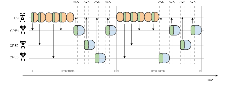
In such circumstance, system can send and receive data from several CPEs during one time frame. Such subslots usage significantly decreases latency in highly loaded by subscribers PtMP, however throughput of the whole PtMP decreases too due to higher amount of the service data used and decrease of payload data size. The system use only one subslot in each direction, then average latency for the subscribers (Round-Trip, in case all subscribers are equally active) would equals number of subscriber stations multiple on time frame size and index "2.5". Usage of several subslots decreases latency proportionally to number of subslots. Meanwhile, the more number of subslots is used, the less would be the part of customer payload within the Uplink time frame. Hence with ratio DL/UL 50%, throughput in Uplink part, would be much less than Downlink. It stands to reason Downlink is dedicated only for transmission of data by the base station, however Uplink is shared among all subscriber stations – consequentially, the more number of subscriber stations, the less amount of Uplink is being provided to each subscriber terminal. Accordingly, it is required to ensure symmetrical sector load – then DL/UL ratio should be lower (for example, 45%). Moreover, DL/UL ratio more than 60% with relatively big number of connected subscriber terminals, does not result in increase of throughput Downlink, because decrease of subslots number drastically increases the latency (whereas throughput decrease and each subscriber unit experience output queue size increase), in consequence, ARQ mechanism does not function correctly, because acknowledgement of data requires a lot of time.
NOTE
Configuration of units in the time division networks (TDMA technology) should be done according to the recommendations specified in the documentation: Link Settings
When it is recommended to use TDMA
Frequency re-use
Same frequency allocation or adjacent frequencies for sectors, mounting on one mast or in the same installation point
The creation of a multisector base station implies the mandatory solution of mutual interference problem. Mutual interference appears between different close installed sectors when they use the same or adjacent frequencies. TDMA development had primary task to solve this problem.
Adjacent frequencies or even same frequencies could be selected due to the following reasons:
- Regulation authority restrict frequency usage
- All other frequencies are overloaded with interferences.
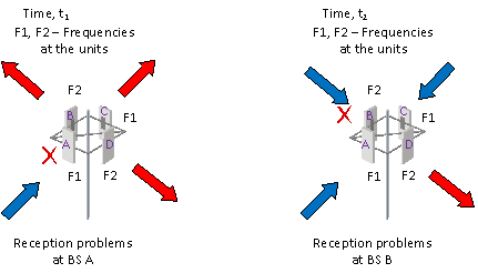
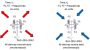
Mutual interference could be excluded, so all sectors would start to transmit and receive data simultaneously. By settings the same parameters for time frame duration and the same ratio for Uplink and Downlink – it is possible to have the same transmission and receiving time for all base station sectors.
Nevertheless, the same time frame size and even the same size for Uplink/Downlink does not guarantee the collisions absence. It is additionally extremely important to start transmission of all sectors and also to start transmission of all subscriber terminals at the same time. The internal clocks of every unit could differ from each other, thus the longer time interval we choose, the more significant the difference could be. TDMA technology includes synchronization of subscriber terminals time with the base station time, otherwise there will be big amount of collisions and retries in Downlink, and collisions could appear.
Sectors synchronization via AUX-ODU-SYNC
The last step is to synchronize time on all sectors of the multisector base station. Special device AUX-ODU-SYNC is required to solve such task. AUX-ODU-SYNC synchronizes its internal clock with the satellite time and provide reference synchronous signal to all connected base station sectors.
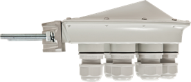
The external synchronization source allows time synchronization (every second start) on several devices (up to 7) with an accuracy less than one microsecond in such manner, that all connected devices would turn on the transmitters at the same moment of time. By doing this way – mutual interference of the neighboring sectors will be fully excluded. In either case single transmitting device by its powerful signal could interferes the other device to receive weak signals coming from the subscriber terminals. Synchronization unit (AUX-ODU-SYNC) has a built-in GPS/GLONASS receiver, and could be even used out of satellite access zone (for example, in the building). In this case, built-in clock generator works out ubiquitous clock pulse to all connected devices. However, it is required to eliminate inter-site interference (two independent base stations, located at some distance from each other), receiving of satellite signal is obligatory. This allows to use GNSS satellite signal as ubiquitous clock pulse.
AUX-ODU-SYNC parameters
- Compatibility with all base station sectors of InfiMAN 2x2 and InfiLINK 2x2 PRO
- Built-in GPS/GLONASS receiver and active antenna
- Provision of clock pulse signal via GNSS
- Provision of on site and inter-site synchronization
- Provision of geolocation information and universal coordinated time (UTC)
- 7 synchronization ports for sectors connection
Connection of AUX-ODU-SYNC requires the specialized cables CAB-SYNC, which provides interfaces conversion and lightning protection.
Correct operation of the described above scheme require two following conditions to be present:
- Base station sector should not “hear” subscriber terminals of the other sectors
- Subscriber terminals should not “hear” signals of other sectors, except own sector signal
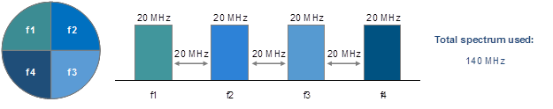
The basic task of inter sector synchronization – provide stable and guaranteed operation of the base station under conditions of limited frequency resource. For example, with TDMA and AUX-ODU-SYNC 4 base station sectors would require only 2 frequencies with channel width 20 MHz each instead of Polling, which in turn would require 4 frequencies with channel width 20 MHz each. Additionally, do not forget to add protective guard intervals between the neighboring frequencies. As see in example, synchronization solution provides increase of performance due to more effective frequency resource utilization. With Polling technology demand to occupy 4 frequency ranges (20 MHz each) with additional guard interval of 20 MHz (same as channel width) between adjacent frequency ranges.
Example 1: BS has 4 TDMA sectors and synchronization unit AUX-ODU-SYNC
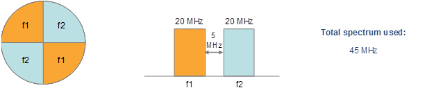
Example 2: BS has 4 sectors with Polling
“Bad” subscriber issue solution
Subscriber terminals in PtMP topologies are rarely have the same distances to the base station. Most likely, everything is different between each subscriber and base station: distance, percentage of Fresnel zone clearance, signal levels, amount of retries and so on. Consequentially, each subscriber terminal communicates with base station on different modulation schemes with different percentage of retries. However, in packet based transmission (Polling technology) time required to transfer data depends on the data total amount, transfer speed and number of repeated attempts (retries). In case the packet sizes are considerable longer, less channel speed (modulation) will be used, more times the data will be re-send (retries) – then more time would be required to finish transfer. The Polling technology works as described.
Therefore, one “bad” subscriber terminal operating only on low modulations or experiencing considerably high retries level, could occupy bigger part of the BS wireless transmission time, which by no means will lead to significant decrease of the throughput of the whole wireless network.
One of the solutions to solve the “bad” subscriber problem is to use TDMA technology. Even in case of high level of retries experiencing by one of subscribers, this particular subscriber will receive new (dedicated) time frame. Herewith the effectivity of other subscriber terminals throughput would be left intact, and consequentially the throughput of the whole wireless network won’t decrease.
SLA provision
TDMA technology allows operators to provide communication channels with guaranteed throughput for each subscriber terminal, ensuring correspondence to Service Level Agreement (SLA).
In practical terms, SLA aimed to ensure good quality of real-time services transport: VoIP and video conferencing. Key parameters influencing real-time application quality operation: packets drops, packets delay and jitter.
In case TDMA technology application, packets latency is stable and almost does not depends on the channel load (retries are not present). In case of retries, latency would increase because each retried packet would be sent in a new time frame and would occupy the same time as the original packet. However, this delay will not affect service of the subscribers who have no problems with data transmission.
Triple play PtMP
In case of demands in multiservice network provision, then selection of WBA solution will be probably the quickest and the most affordable way to provide the services.
High quality service guarantee could be achieved only with TDMA technology.
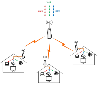
With Polling technology the implementation of the throughput of the wireless network in PtMP topology, most likely would be even higher than the throughput with TDMA technology, however jitter would be small and stable only with TDMA technology. Unstable jitter leads to significant degradation of real time application services, especially for VoIP.
Operation in severe conditions: nLoS, over the water links
TDMA technology ensures a stable wireless communication channels even in the absence or limitation of clear Line-of-Sight zone (buildings in city, forest, over the water links). Such conditions could cause the creation of multiple reflected signals from the obstacles. One part of the reflected signals will scatter, another part will reach receiving device using longer path or will return to transceiver with some delay (at long links the delay could be several dozens of seconds). In such way, the reflected signal can mix with wanted signal (for example, with acknowledgement packet ACK, which should be sent as fast as possible after data receiving) and cause interference or signal distortion.
TDMA solves such problem by the introduction of a protective interval (guard) at the end of each frame, which admits to delay start of transmission until all reflected signal fade. The guard interval duration can be changed in configuration of the base station.
When it is recommended to use Polling
Operation in heavy noise environments (Interference)
Usage of TDMA technology under heavy interferences leads to increased retries. Unfortunately, in TDMA every subscriber terminal cannot immediately repeats to send corrupted data – instead retries would be sent in the next available time frame. Therefore, increased delays are consequence of TDMA operation in environments with heavy interferences.
Unlike TDMA, with Polling the data to be repeated would be sent almost immediately after the error detection in the previous communication packet.
Narrow bands operation (5 MHz and 10 MHz)
It is not recommended to use TDMA for PtMP topologies with channel width 10 MHz or even 5 MHz, cause performance would decrease. Service information (Sync, guard) increases proportionally with the channel width decrease, therefore payload data decreases in proportion.
The time frame duration changes from 1 to 10 ms with the step of 0.2 ms. Of course, it makes no sense to decrease the size to the lowest value cause amount of the service information is constant and doesn’t change, however in proportional comparison with the total frame size, service information occupies more time with every time frame duration decrease. In order to control payload size, the radio interface statistic includes the special parameter which shows the current payload share (Tx Time Limit/ Rx Time Limit) in microseconds. Such parameter value cannot be lower than 0, in either case the sustentation of the wireless link would be impossible.
Moreover, with relatively big number of subscribe units the ratio of DL/UL more than 60%/40% practically won’t increase throughput in Downlink, cause subslots number decreases will result in latency increase, and won’t allow ARQ mechanism to work effectively – the acknowledgement of data delivery would require too much time. In case to prevail of Uplink traffic, such situation is possible for video surveillance systems, the ratio of DL/UL could be decrease to minimum value with confidence, creating by this maximum number of UL subslots. TDMA technology efficiency increases with growth of modulation speed and channel width size.
As the result, it is recommended to use system with PtMP topology in narrow bands (5 and 10 MHz) with Polling technology. TDMA technology could be used in narrow bands only in case the total volume of traffic is relatively small, but SLA requirements are very strict, for example, the wireless links are devoted for VoIP traffic transport.
Conclusion
TDMA technology allows to create multisector base station with a high density of available frequencies usage. In other words, current available frequency resource could be utilized more effectively in case of migration to TDMA technology. Moreover, TDMA provides tool to ensure stability under near LoS conditions and for over the water links.
However, TDMA only elaborates with Polling technology without replacing it. In case of strong interference or in narrow bands, Polling is the recommended technology to rely on.
Both technologies ensure maximum effective operation of InfiNet Wireless equipment in various environments and projects.
Links
See also:
- Upgrade from Polling to TDMA.
- Radio link settings in the marker access networks (Polling technology).
- Radio link settings in the time division access networks (TDMA technology).
- Connection to the synchronization unit.
Download firmware: