Page tree
Skip to end of metadata
Go to start of metadata

Successfully pass the free certification exam at IW Academy and become an Infinet Certified Engineer.

To the certification exam

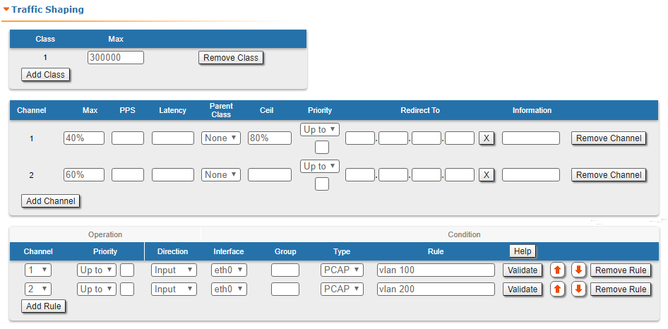
The "Traffic Shaping" section allows to manipulate the data streams flowing through the device. Up to 200 logical channels can be created, characterized by different properties (such as priority levels and data transfer rates), and then the data streams can be assigned to these logical channels according to the special rules, previously created. In order to configure distribution of the transmit rate between several channels, can be created the class.

In the default configuration, there is no channel or class created.

Create the class by clicking the "Add Class" button, to set the transmit rate redistribution for one or more channels.

ParameterDescription
ClassService class number in the range 1-200
MaxMaximal available transmit rate in Kbps

You can delete an existed class by clicking the corresponding "Remove Class" button.

Figure - Traffic Shaping options

In order to prioritize the data flows and/or to set the data transfer rates, create the logical channels by clicking the "Add Channel" button.

The following parameters can be configured in the "Traffic Shaping" section for the logical channels:

Logical channel parameterDescription

Channel

  • Logical channel number (1-200 allowed)

Max

  • Set the maximum transmit rate (in Kbps)
  • You can limit the data traffic within a logical channel to a certain rate of kilobits per second
  • The value can also be set in percentage of the class.

PPS

  • Set the maximum packet per second rate (in pps)
  • You can limit the data traffic within a logical channel to a certain rate of packets per second

Latency

Set latency value (between 5 ms and 200 ms) for each channel (queue length)

  • Leave it empty for the default value
  • Determines the maximum time the packets can to stay in the queue
  • Packets are discarded if they are still in the queue after the value set for latency is reached
Parent Class
  • Establish affiliation to a class.
Ceil
  • Available only if the parent class is specified.
  • Set the maximum non-guaranteed transmit rate in a percentage of the higher-class band or in Kbps.
  • If no value is specified, the free transmit rate of the class is distributed evenly between the channels, depending on the load.

Priority

  • Allocate the priority for all the packets going through a specific rule:
    • Up to” - used to increase the packet priority to the specified value only if the processed packet has a lower priority
    • Set” - used to assign a new priority regardless of the value already assigned to the packet

Redirect To

  • Set the gateway IP address (only for the router mode)
  • The whole stream is redirected to the specified IP-address regardless of the current routing configuration
  • It  may be useful when the router serves as a network access unit and two or more different clients want to access different providers through one unit

Information

  • Set a description for the logical channel created
Table - Logical channel parameters

You can delete an existed logical channel by clicking the corresponding «Remove Channel» button.

You can create a traffic shaping rule by clicking the «Add Rule» button.

Traffic shaping rule parameterDescription

Channel

  • Select the logical channel from the dropdown list
  • All the parameters of this rule are applied to this channel

Priority

  • Set the priority for the packets going through the new rule of the filter:
    • Up to” - used to increase the packet priority to the specified value only if the processed packet has a lower priority
    • Set” - used to assign a new priority regardless of the value already assigned to the packet

Direction

  • Set the input/output direction for applying the new rule:
    • Input” - the rule is used to process inbound traffic
    • Output” - the rule is used to process outbound traffic and for post-routing packet filtering

Interface

  • Set the interface for applying the new rule
  • All the available interfaces are displayed in the dropdown list (physical and logical)
  • If “any” option is used, the rule is applied to all available interfaces

Group

  • Set the Switch Group number for the applying of the new rule
  • The Switch Group must be prior created

Rule

  • Set the packet capture filter
  • It is the same syntax called “PCAP expression”, as in the "Switching" section
  • Refer to the filter expression syntax description above
  • Validate the rule by clicking the «Validate» button
Table - Traffic shaping rules

You can delete an existed traffic shaping rule by clicking the corresponding «Remove Rule» button.