Successfully pass the free certification exam at IW Academy and become an Infinet Certified Engineer.
Introduction
To increase the wireless network throughput built on InfiLINK 2x2 / InfiMAN 2x2 families devices (R5000 series) the network can be partially or completely upgraded to the InfiLINK Evolution / InfiMAN Evolution families (Evolution series). Datasheets on these families are presented on the Infinet's website:
The document contains recommendations how to upgrade the wireless network from the R5000 series to Evolution and limitations that must be taken into account when R5000 and Evolution devices operate together in one network.
InfiLINK Evolution / InfiMAN Evolution advantages
InLINK Evolution / InfiMAN Evolution key features compared to InfiLINK 2x2 / InfiMAN 2x2:
Evolution devices operate in 4.9–6.4 GHz frequency bands, which allows to use the same devices in the 5 and 6 GHz bands.
Instant DFS technology support on firmware level. Evolution devices continuously perform background spectrum monitoring and seamlessly change channel to the least noisy frequency without link interruption, taking into account the spectrum conditions at the location of all connected devices.
The ability to operate in the 80 MHz band increases the Evolution devices performance twice compared to R5000. Infinet devices peformance data is shown in article "Performance of the Infinet Wireless devices".
All Evolution devices support the QAM256 5/6 modulation-code scheme allowing to get a performance advantage of up to 30% compared to the R5000.
10 modulation-code schemes allow to adapt to the radio deterioration by performance reduction with a small steps.
- The spectrum allocated to the link is used by the InfiLINK Evolution family with maximum performance due to the spectral efficiency of 8.375 bit/s/Hz.
- InfiMAN Evolution base station sector could be integrated into existing optical networks thanks to second SFP port.
InfiLINK Evolution / InfiMAN Evolution and InfiLINK 2x2 / InfiMAN 2x2 technical parameters comparison is given in the table below:
| Parameter | InfiLINK 2x2 PRO | InfiLINK 2x2 LITE | InfiLINK Evolution | InfiMAN 2x2 | InfiMAN Evolution | |||
|---|---|---|---|---|---|---|---|---|
| Base station | Subscriber Terminal | Base station | Subscriber Terminal | |||||
Frequency range, MHz |
|
|
|
|
|
|
| |
Channel width, MHz |
|
|
|
|
| |||
Transmit power, dBm |
|
|
|
|
|
|
| |
Modulation coding schemes |
|
|
|
|
| |||
Throughput, Mbps | 40 MHz |
|
|
|
|
|
|
|
Max value |
|
|
|
|
|
|
| |
| Wired Interfaces |
|
|
|
|
|
|
| |
Proprietary technologies |
|
|
|
|
| |||
TDD sync |
|
|
| |||||
Multiple access method |
|
|
|
|
|
|
| |
| Consumption, W |
|
|
|
|
|
|
| |
| Power options |
|
|
|
|
|
|
| |
*-Roadmap item.
Limitations
Limitations in device configuration and design must be taken into account during the network upgrade from R5000 series to Evolution, and R5000 with Evolution devices joint operation in one network.
NOTE
InfiLINK Evolution / InfiMAN Evolution devices in the “transient” mode are guaranteed to work only with devices based on the H08 and H11 platforms of InfiLINK 2x2 and InfiMAN 2x2 families devices. Work with devices based on other platforms, for example, H05, H06 and H07 is not guaranteed.
Configuration Settings
- Firmware version
The Evolution series devices support time division multiple access technology (TDMA). The devices are delivered only with TDMA firmware. Thus, the R5000 devices must be upgraded to the TDMA firmware version. Procedure how to upgrade the network from Polling firmware to TDMA are provided in the section "Upgrade from Polling to TDMA".
- Channel width
The 80 MHz channel width is not supported on InfiLINK 2x2 / InfiMAN 2x2 devices.
Duplex modes
The 1000BaseTX-fullduplex, 1000BaseTX-fullduplex manual duplex modes are not supported on the InfiLINK 2x2 LITE / InfiMAN 2x2 subscriber terminal devices.
- Greenfield mode
Greenfield mode is not supported on InfiLINK Evolution / InfiMAN Evolution devices. The Greenfield mode should be disabled on the R5000, as it leads to frame incompatibility at the header level.
NOTE
It should be noted that Greenfield mode disabling on R5000 devices will reduce the performance on 10-15 %. This is due to the algorithm disabling that optimizing frames transmitted via a wireless link.
- Scrambling mode
Scrambling mode is not supported on InfiLINK Evolution / InfiMAN Evolution devices. Scrambling mode must be disabled on R5000 devices, otherwise the data corruption process will be observed in the wireless link.
- Bitrate TX
- InfiLINK 2x2 / InfiMAN 2x2: 30000, 60000, 90000, 120000, 180000, 240000, 270000, 300000 (Kbps).
- InfiLINK Evolution / InfiMAN Evolution: 65000, 130000, 195000, 260000, 390000, 520000, 585000, 650000, 780000, 866700 (Kbps).
Physical connection
- Wired Interfaces number
- InfiLINK 2x2 LITE / InfiMAN 2x2 subscriber terminals: 2х FastEthernet (RJ45).
- InfiLINK Evolution / InfiMAN Evolution subscriber terminal: 1xGE (RJ45).
- PoE-out
PoE-out mode is supported only on InfiLINK 2x2 LITE and InfiMAN 2x2 subscriber terminals.
- IDU-CPE-DC power supply
The IDU-CPE-DC power supply can be used to power only the InfiLINK 2x2 LITE and InfiMAN 2x2 subscriber terminals.
- CAB-SYNC cable
To connect the AUX-ODU-SYNC device to wireless devices, specialized cables must be used:
- InfiMAN 2x2 base station / InfiLINK 2x2 PRO: CAB-SYNC cable.
- InfiMAN Evolution base station: CAB-SYNC-E cable.
CAB-SYNC and CAB-SYNC-E datasheets are presented on the Infinet company's website in the section "Accessories".
R5000 and Evolution models compliance
The table below provides recommendations for replacing the InfiLINK 2x2 / InfiMAN 2x2 models with the InfiLINK Evolution / InfiMAN Evolution.
| PtP | PtMP | ||
|---|---|---|---|
InfiLINK 2x2 | InfiLINK Evolution | InfiMAN 2x2 | InfiMAN Evolution |
| R5000-Mmx/5.300.2x500.2x23 | E5-ST25 / E6-ST25 | Base station | |
| R5000-Mmx/5.300.2x500.2x26 | E5-ST28 / E6-ST28 | R5000-Qmxb/5.300.2x300.2x21 | E5-BSQ |
| R5000-Mmx/5.300.2x500.2x28 | E5-ST28 / E6-ST28 | R5000-Mmxb/5.300.2x500.2x16 | E5-BSI |
| R5000-Omx/5.300.2x500 | E5-STE / E6-STE | R5000-Omxb/5.300.2x500 | E5-BSE |
| R5000-Mmx/6.300.2x200.2x24 | E6-ST25 | R5000-Lmnb/5.300.2x500.2x16 | E5-BSI |
| R5000-Mmx/6.300.2x200.2x27 | E6-ST28 | R5000-Lmnb/5.300.2x500 | E5-BSE |
| R5000-Omx/6.300.2x200 | E6-STE | R5000-Mmxb/6.300.2x200.2x16 | E6-BSI |
| R5000-Smn/5.300.2x300.2x19 | E5-ST23 / E6-ST25 | R5000-Omxb/6.300.2x200 | E6-BSE |
| R5000-Smn/5.300.2x300.2x23 | E5-ST23 / E6-ST25 | R5000-Smnb/6.300.2x200.2x16 | E6-BSI |
| R5000-Smn/5.300.2x500.2x23 | E5-ST25 / E6-ST25 | R5000-Lmnb/6.300.2x200 | E6-BSE |
| R5000-Smn/5.300.2x300.2x26 | E5-ST25 / E6-ST25 | Subscriber terminal | |
| R5000-Smn/5.300.2x500.2x26 | E5-ST28 / E6-ST28 | R5000-Smnc/5.300.2x300.2x19 | E5-ST23 / E6-ST25 |
| R5000-Smn/5.300.2x300.2x28 | E5-ST28 / E6-ST28 | R5000-Smnc/5.300.2x300.2x23 | E5-ST23 / E6-ST25 |
| R5000-Smn/5.300.2x500.2x28 | E5-ST28 / E6-ST28 | R5000-Smnc/5.300.2x300.2x26 | E5-ST25 / E6-ST25 |
| R5000-Lmn/5.300.2x300 | E5-STE / E6-STE | R5000-Smnc/5.300.2x300.2x28 | E5-ST28 / E6-ST28 |
| R5000-Lmn/5.300.2x500 | E5-STE / E6-STE | R5000-Lmnc/5.300.2x300 | E5-STE / E6-STE |
| R5000-Smn/6.300.2x200.2x19 | E6-ST18 | R5000-Smnc/6.300.2x200.2x19 | E6-ST18 |
| R5000-Smn/6.300.2x200.2x24 | E6-ST25 | R5000-Smnc/6.300.2x200.2x24 | E6-ST25 |
| R5000-Smn/6.300.2x200.2x27 | E6-ST28 | R5000-Smnc/6.300.2x200.2x27 | E6-ST28 |
| R5000-Lmn/6.300.2x200 | E6-STE | R5000-Lmnc/6.300.2x200 | E6-STE |
Upgrade Scenarios
Point-to-Point topology
In order to minimize the network outage due to the devices replacement we recommend to replace the device first at one end of the wireless link and then at the other. To do this:
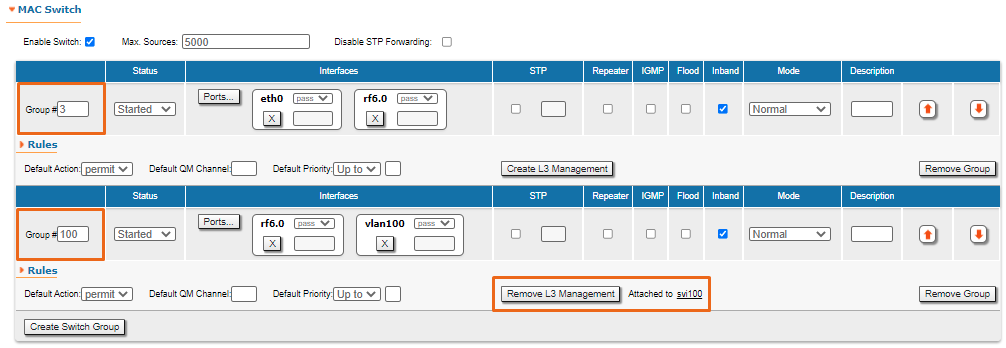
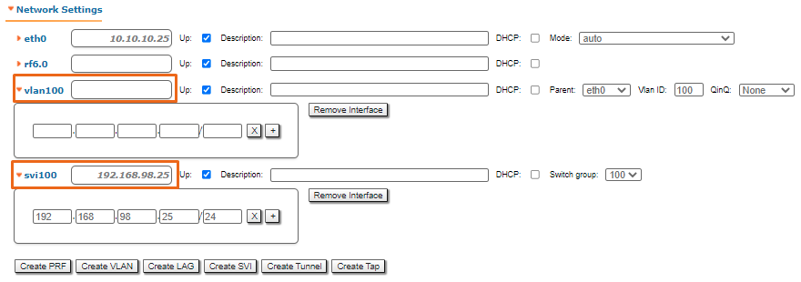
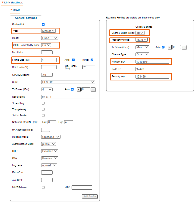
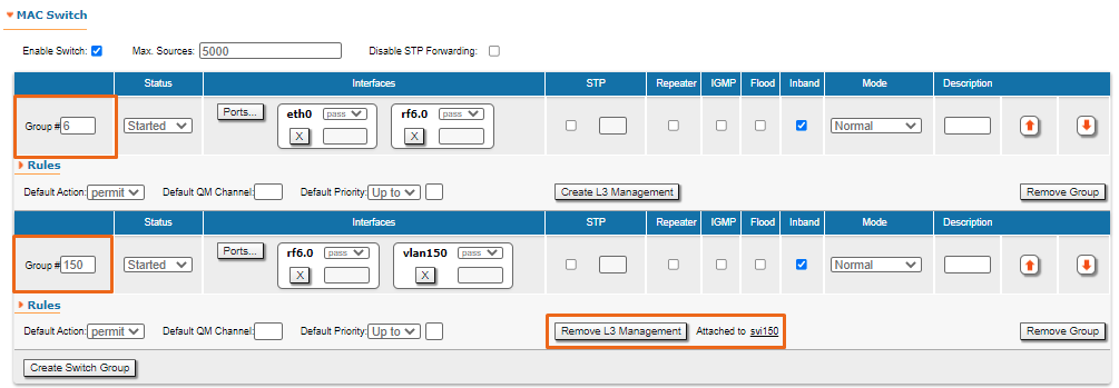
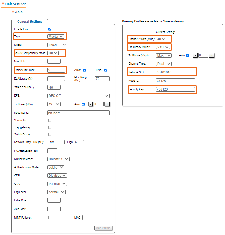
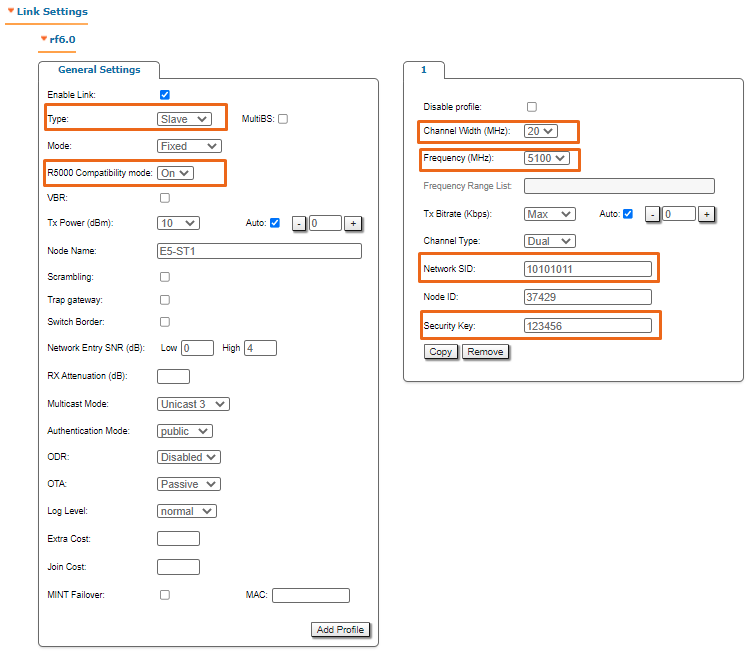
- Configure the switching and radio parameters on the InfiLINK Evolution device that are equal to the replaced InfiLINK 2x2, except "Network SID" value.
- Enable R5000 Compatibility mode.
- Install the InfiLINK Evolution device next to the one being replaced. The directions of the antennas must match. Connect the device to the power supply network.
- On the remote device, change the "Network SID" to the value set on InfiLINK Evolution.
- The wireless link will have to be established between the InfiLINK Evolution and InfiLINK 2x2.
- Check the antennas alignment. Instructions are provided in the section "Antenna alignment".
Example of upgrading a Point-to-Point network topology
Point-to-Multipoint topology
To increase the network throughput, we recommend:
- Replace the base station sector in accordance with the recommendations of the table in the section "R5000 and Evolution models compliance".
- Replace critical subscriber terminals.
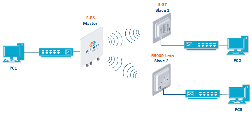
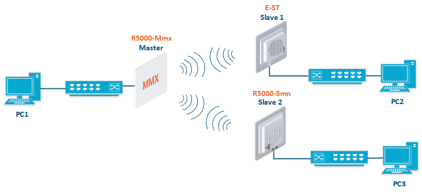
Example of upgrading a Point-to-Multipoint network topology


