When installing on poles without lightning protection systems, the ODU or external antenna should be placed on the pole at a height that is at least 1 meter below the top of the pole. In this case, there is a significant probability that the lightning strikes the pole and not the ODU or antenna. The pole should be properly grounded: connected to the building lightning protection circuit according to your local regulations. When lightning strikes the external antenna, the current goes through the coaxial cable to the ODU case, which is connected through the ODU clamp to the pole - the pole is grounded. The direct lightning strike to the FTP service cable (ODU-IDU) is partially terminated on the grounded IDU case. Partial termination means that the direct lightning strike will probably destroy an FTP cable. The service cable pickups from the electromagnetic impulses are terminated on the IDU case by the winding shield, and further - on the IDU grounding.
NOTE
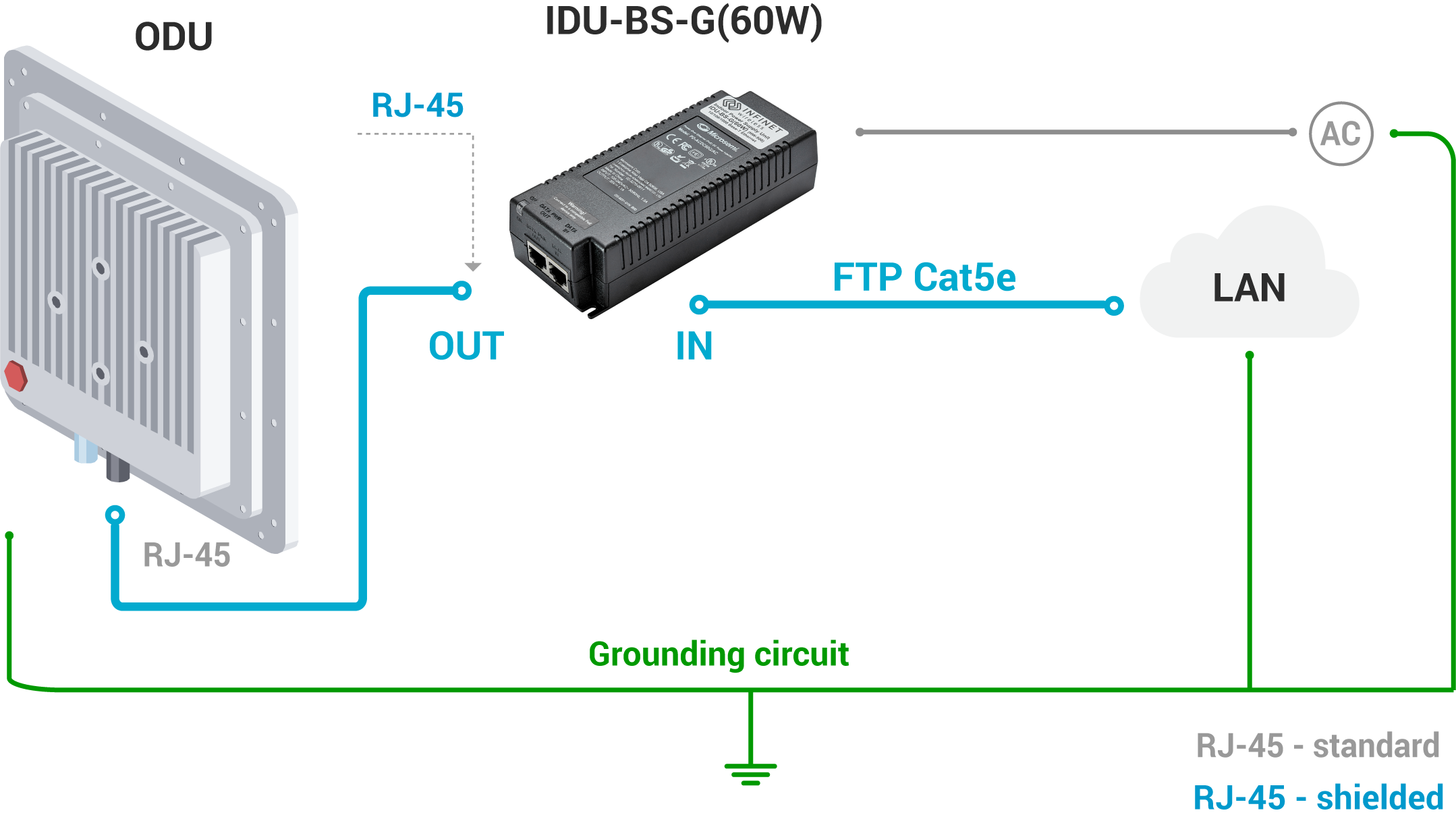
The end of the FTP service cable that is connected to IDU should be assembled with a shielded RJ-45 connector. The other end of the FTP service cable (connected to ODU) should be assembled with unshielded RJ-45 connector.
IDU is grounded via a three-conductor power cord and a grounded socket. The data & power wires pickups are terminated via IDU protection scheme (three-conductor power cord and a grounded socket).
NOTE
Antenna pole, tower, ODU and lightning arrestor should be connected to the common ground ring. Grounding cables should be no less than 10AWG thick and must use corrosion-resistant connectors. At the end of the FTP cable that connects to the IDU should be used an RJ-45 connector with grounding. At the other end of the cable (connected to the ODU) should be used an RJ-45 connector without grounding.
Special attention should be paid if the antenna used is not DC-shorted. In this case, an additional lightning arrestor should be used between the antenna and ODU.
Grounding diagram is shown in the picture below.