...
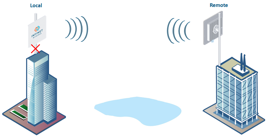
1.No access to the local unit
...
Checking the network infrastructure
...
If there is no power, it is necessary to check the power supply, connectors, the Ethernet cables integrity.
...
| Gliffy Diagram | ||||||
|---|---|---|---|---|---|---|
|
Access to the unit recovery
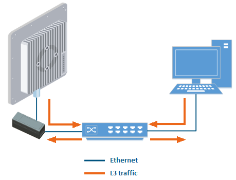
If the power indicator is on and there is connection via the Ethernet interface, connect to the device directly as it is shown in the scheme below. Make sure that the IP address of the PC is in the same subnet as the IP address of the device. You can restore the IP address and reset the device to the factory settings using the ERConsole utility.
...
Before starting the access restoring procedure, it is recommended to install the following software:
...
If you were able to access the device by connecting directly, try to determine the possible reason for the unavailability through the network. Pay attention to the wired interface statistics.
...
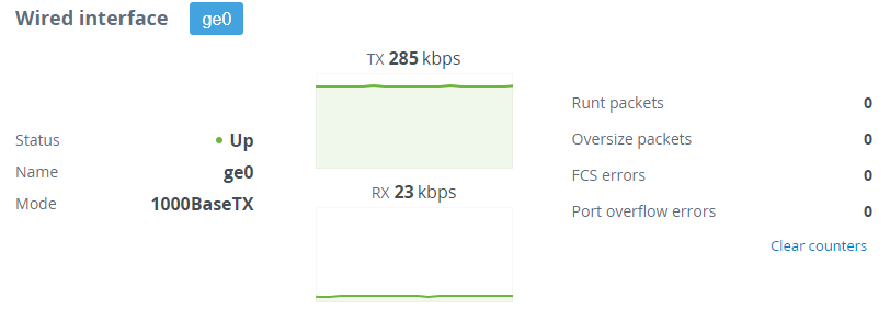
In the "Wired interface" section, you can monitor the Ethernet interface status and its traffic load for reception and transmission. The wired interface statistics is on the right side and can be reset by clicking the "Clear counters" button. Pay attention to the FCS errors number which indicate a violation of data integrity during transmission over the wired segment. Also, the problem can be caused by a queue (port) overflow or inappropriate frame size (runt and oversize).
...
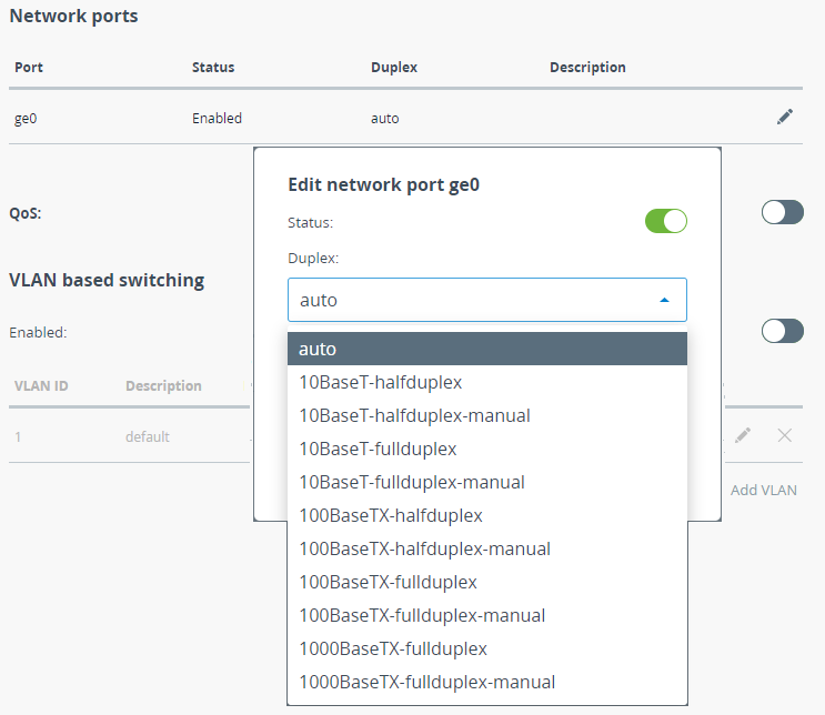
Pay attention to the duplex mode on the network devices connected to the wireless bridge. The duplex mode can be changed in the "Switch" - "Network Ports" section. We recommend setting the autonegotiation mode provided by the Ethernet standard. The problem can occur while connecting two devices with different duplex settings. For example, if one device has the autonegotiation mode, and the other - fixed full duplex mode.
...
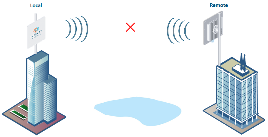
2. Wireless Wireless link is not established
...
...
Pre-configuration in the lab
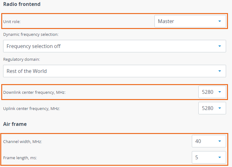
Before installing the devices on site, we recommend to configure the basic parameters in the lab and to make sure that the link is establishing. Step-by-step instructions for a wireless link configuration are given in the Link Pre-configuration in the lab article.
...
- Channel Width.
- Frequency.
- Frame length.
- Access key.
...
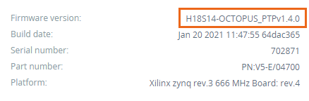
Checking the firmware version
In the "Maintenance" section, make sure that the same firmware version is installed on both devices. The latest software versions can be downloaded from the official Infinet FTP server.
...
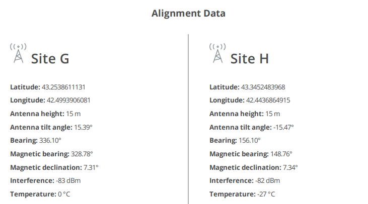
Checking the installation requirements
Check if the suspension height, azimuth and elevation of the antenna match with the values obtained from InfiPLANNER. Make sure that the obstacles on the path profile are not higher than those specified during the planning phase.
...
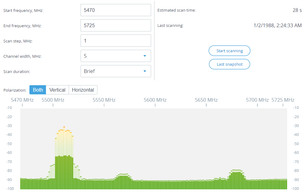
Interference detection
Using the built-in Spectrum Analyzer tool, scan the air on both sides of the link to make sure there is no interference that could corrupt the signal on the device's operating frequency and on the adjacent frequencies. To get accurate information about the frequency, hover the mouse cursor over it. The pop-up window below provides information about frequency, maximum signal level, average signal level. The indicators show the signal level in dBm. For operation at the highest modulations, the RSSI parameter value should be in the range of -60 ...- 40 dBm. To get the spectrum scanning results on the remote device, use the "Last snapshot" button.
...
3. The The wireless link is established, but there is no access to the remote device
...
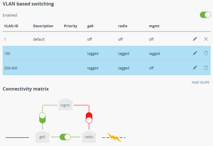
In the "Switch" section of the web interface, make sure the VLAN-based switching settings are configured in accordance with the network architecture. Make sure the connectivity between the "ge0" and "radio" interfaces is enabled.
...
Checking the switch settings on the remote device
...
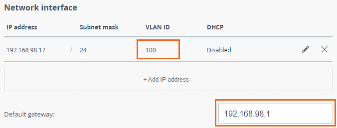
In the "Network" section, make sure the correct VLAN ID is assigned to the management IP address and the default gateway is configured in accordance with network architecture..
...
4. The wireless link throughput is lower than expected
...
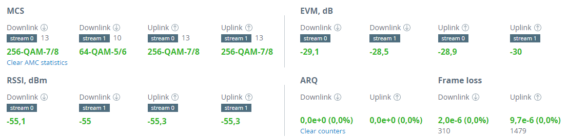
Perform an antenna alignment using the built-in utility, especially in case the RSSI and EVM values are low.
...
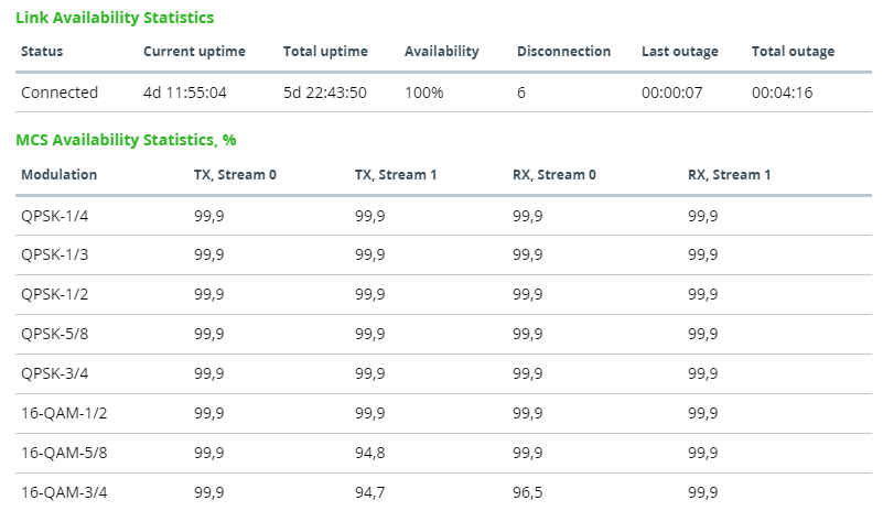
Availability statistics
To analyze the wireless link availability time, proceed to the corresponding statistics in the "Dashboard" - "Availability statistics" of web interface. The opened window displays the link operation statistics for each modulation.
...
5. Common errors in configuration
...
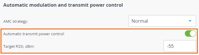
Enable the automatic transmit power control (ATPC) in order to increase the operational life of the devices. Set the "Target RSSI" parameter to values from -40 to -60 dBm.
...
Frame length
Make sure the selected frame size ensures the best performance for your wireless system. A short frame will transmit less payload than a long one, however it ensures a smaller delay.