...
In this section procedure about remote management of the the InfiNet Wireless R5000 units units, using network logical interface SVI and auxiliary network logical interface VLAN, is described.
...
| Scroll Ignore | |
|---|---|
|
Switching process in WANFleX
...
...
InfiNet Wireless units use proprietary protocol MINT above Layer 2 and lower than Layer 3 in reference to OSI Layer model.
| Center | |||||
|---|---|---|---|---|---|
|
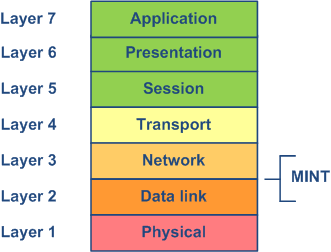
MINT stands for Mesh Interconnection Network Technology which points to the technology for networks based on arbitrary connections. The most important feature of MINT architecture MINT architecture is its ability to present any wireless (or even sometimes wired) network as a flat Ethernet segment, and radio interface connected to this network will act as usual Ethernet interface (virtual).
MINT protocol MINT protocol has built-in capability to establish connections to MINT neighbors MINT neighbors and share information of other connected MINT neighborsMINT neighbors. There is no need to configure and adjust MINT protocol MINT protocol settings. MINT unique MINT unique feature is the ability to choose optimal paths in a network with multiple nodes and connections. Each neighbor connection can be evaluated as special value – i.e. "Cost". Its physical meaning – an estimated time for packet delivery measured in conventional units. The less the "Cost", the higher probability that this path will be chosen. The "Cost" of each connection is constantly changing according to link parameters including radio values (signal-to-noise levels), type of modulation speed used, number of errors and retries, link load and other parameters thus allowing quickly switching to an alternative route if its cost will be lower than for the current one.
So, the switching process is done by MINT protocolMINT protocol. The switching in MINT is MINT is done ONLY between two units or more. Each time you have some data for switching you should consider at least two devices as single switch path. Right now lets treat two InfiNet Wireless units as virtual “spatial” switch which has only two physical Ethernet ports, so you can just simply switch all traffic between two Ethernet ports (each port belongs to different unit).
However, in order to differentiate between traffic and its destination when you have more than two devices or more than one traffic type is to use VLAN tagging. In MINT we MINT we use Switch Group ID to make traffic differentiation. That is why all VLAN tags VLAN tags (or any other filter criteria) should be used to assign traffic to different Switch Group. While traffic resides in MINT domain it will be transferred only between InfiNet units with configured and same fixed Switch Group ID number. Switch Group is a logical entity which allows switching between physical ports binded to Switch Group.
So, all traffic destined for switching is transported by MINT protocol MINT protocol in special Switch Groups. Switch Groups are mostly used as container to transport VLAN tagged VLAN tagged traffic through MINT networkMINT network. Therefore, MINT network MINT network can be viewed as one virtual distributed switch where border nodes act as external ports of the virtual switch. Switch task is to transparently transport packets from one external port to another one (other ones). Important to understand that switching groups should be created only on the nodes where packets enter from "outside" network ("outside" relative to MINT).
Therefore, if the Switch Group was created and Ethernet port (for example, "eth0") and Radio port (for example, "rf5.0") were added then the switching from "eth0" to "rf5.0" and vice versa has been enabled.
SVI is is special logical interface that can be assigned to Switch Group therefore one can access and manage the unit via dedicated Switch Group and via dedicated VLAN.
| Note | ||
|---|---|---|
| ||
Detailed information about MINT is described in the document "R5000 - MINT & Mobility" - White paper, which is available via httphttps://academy.infinetwireless.com/productsen/materials#white-papersdocuments (free registration is required). |
...
. |
Management and data traffic configuration
Recommended method
In default configuration, in "MAC Switch" section, switch group #1 is available with "eth0" and "rf5.0" interfaces and with no additional rules. In this case, all frames coming to the unit from local Ethernet interface will be delivered to the opposite side of the link and sent out the remote Ethernet interface and vice versa. This simple configuration will enable transparent switching - all packets will go through the link unchanged; “VLAN tags”, “QoS” fields, etc. will be preserved.
Nevertheless, in case of remote VLAN management in order to separate customers traffic and management at least two switch groups should be used: one switch group for management, another switch group for data traffic.
In the example below, switch group #100 will be used for the management via VLAN (VLAN ID 100) and the switch group #1 (created by default) - for the data traffic.
- Step 1
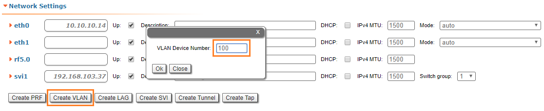
In "Basic Settings" → "Network Settings" section create VLAN 100 interface by clicking "Create VLAN" button
| Center |
|---|
|
- Step 2
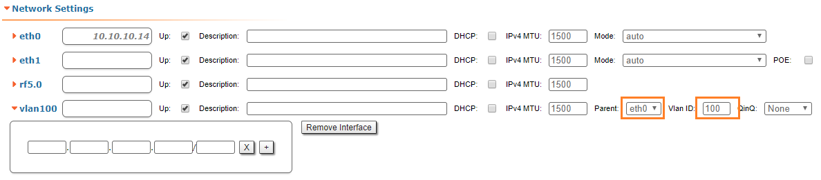
Set required VLAN ID and make sure "eth0" is selected as a parent interface
| Center |
|---|
|
- Step 3
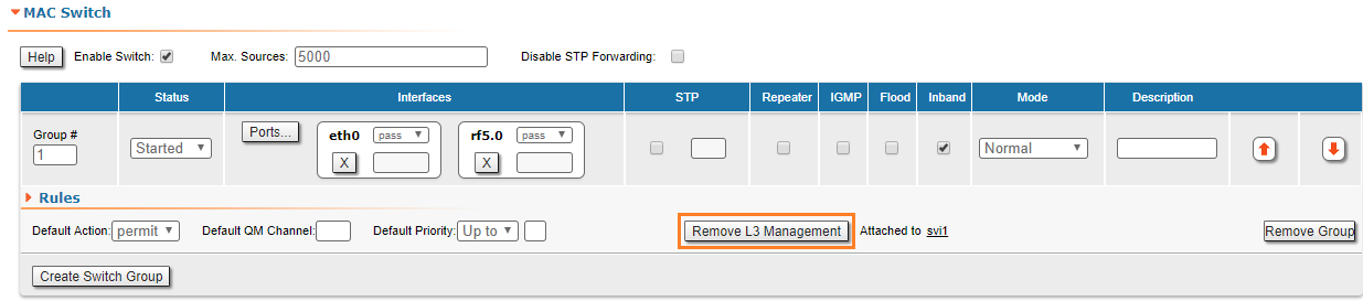
In "Basic Settings" → "MAC Switch" section, we have to delete the "svi1" interface (which is available in the default configuration) by clicking the "Remove L3 Management" button
| Center |
|---|
|
- Step 4
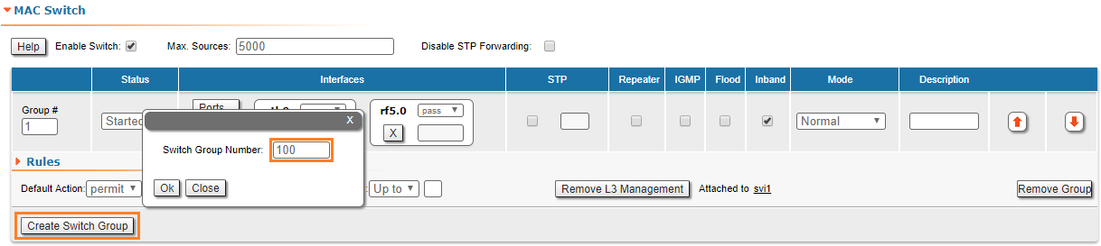
In "Basic Settings" → "MAC Switch" section, create switch group #100 for the management by clicking the "Create Switch Group" button
| Center |
|---|
|
- Step 5
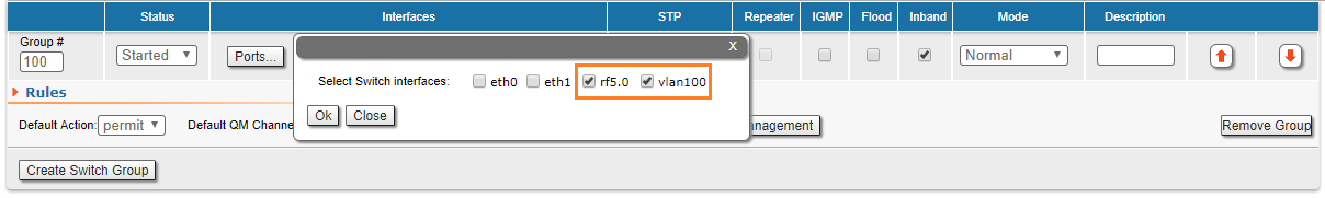
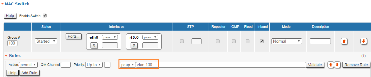
Add "vlan100" and "rf5.0" interfaces to the switch group #100
| Center |
|---|
|
| Note | ||
|---|---|---|
| ||
In case the VLAN interface is added to the switch group, traffic with the corresponding VLAN ID received by parent interface enters the switch group (no additional rules are required), 802.1q tag will be removed |
- Step 6
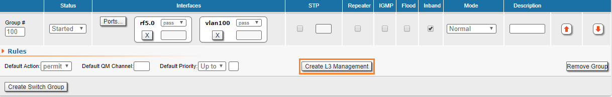
To create "svi" interface connected to this group click the "Create Switch Group" button
| Center |
|---|
 |
| Warning | ||
|---|---|---|
| ||
In software verions before "MINTv1.90.33" / "TDMAv2.1.7", the "Create management" button is not used for this setting method, it is necessary to create "svi100" interface by clicking "Create svi" button in "Basic Settings" → "Network Settings" section and add it to the switch group #100
|
- Step 7
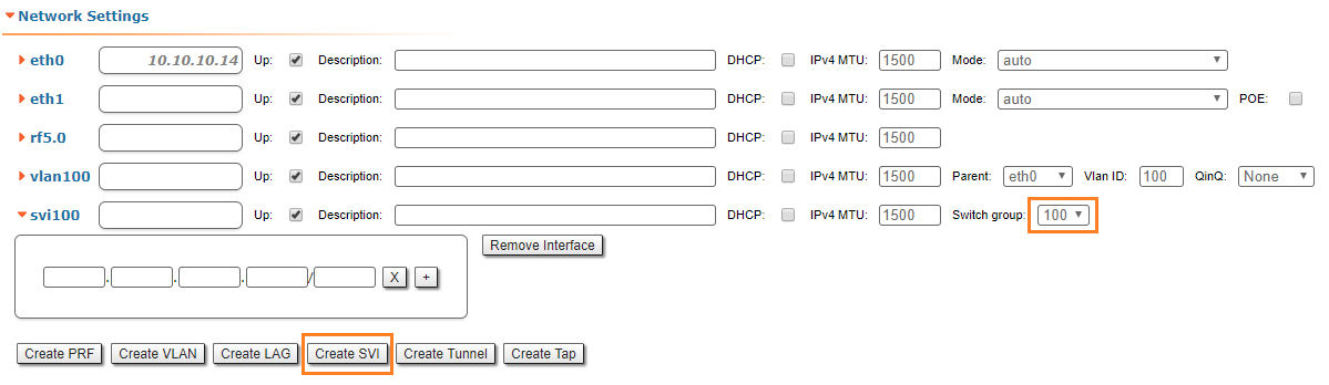
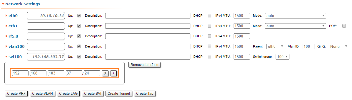
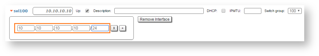
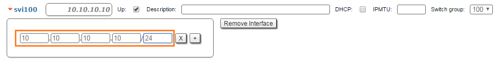
In "Basic Settings" → "Network Settings" section assign IP address to the "svi100" interface (don't forget about netmask)
| Center |
|---|
|
- Step 8 (Optional)
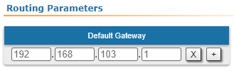
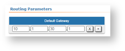
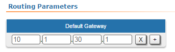
Set the default gateway IP address
| Center |
|---|
|
- Step 9
Before saving the current configuration, please make sure that you can access the unit on VLAN 100. If you connect the PC directly to the unit, you have to set VLAN 100 for the outgoing traffic at the network interface.
- Step 10
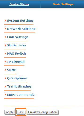
Try the new configuration temporarily by clicking on the "Test" button
| Center | |||||
|---|---|---|---|---|---|
|
- Step 11
If everything works properly, you can save the settings performed in all sections of the "Basic Settings" page, by clicking the «Commit» button.
| Center | |||||
|---|---|---|---|---|---|
|

| Note | ||
|---|---|---|
| ||
Read information at the "Apply, Test and Preview buttons for the configuration" section in order to find out the output of the «Apply», «Test» and «Preview» buttons for the new configuration performed. |
We have created switch groups for management and data traffic, special interfaces for vlan management and we have set an IP address to the svi management interface.
We have to perform the same settings for the second unit and check the connectivity with VLAN 100 to each unit.
Alternative (not recommended) method
This method is used for units configuration with software verions before "MINTv1.90.33" / "TDMAv2.1.7".
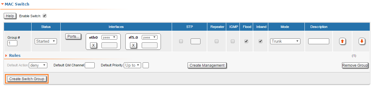
In default configuration, in "MAC Switch" section, Switch switch group #1 is available with "eth0" and and "rf5.0" interfaces interfaces added and with no additional rules. In this case, all frames coming to the unit from local Ethernet interface will be delivered to the opposite side of the link and sent out the remote Ethernet interface and vice versa. This simple configuration will enable transparent switching - all packets will go through the link unchanged; “VLAN tags”, “QoS” fields, etc. will be preserved.
Nevertheless, in case of remote VLAN management in order to separate customers traffic and management at least two switch groups should be used: one Switch Group for management, another Switch Group for customers trafficdata traffic.
In the example below, the switching group 100 will be used as the management group, the management will be performed via VLAN with the same number. For data traffic, we will use the switching group 1, created by default.
- Step 1
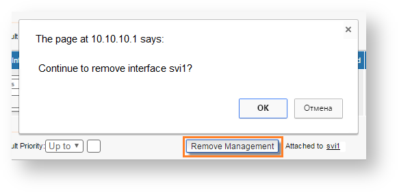
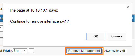
In "Basic Settings" → "MAC SwitchMAC Switch" section, we have to delete the "svi1" interface (which is available in the default configuration) by clicking the «Remove Management» button:
| Center | |||||
|---|---|---|---|---|---|
|
- Step 2
In order to create two Switch Groups (or only add additional Switch Group for switch group for the management traffic ) go to the "Basic Settings" → "MAC Switch" section and click "Create Switch Group" button.
| Center | |||||
|---|---|---|---|---|---|
|

- Step 3
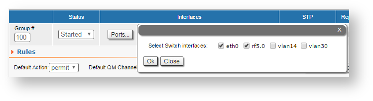
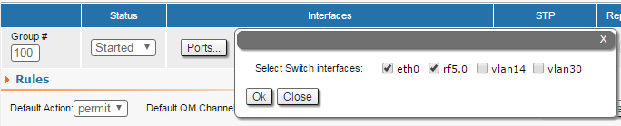
Add both wired "eth0" and radio "rf5.0" interfaces to this switch group
| Center | |||||
|---|---|---|---|---|---|
|
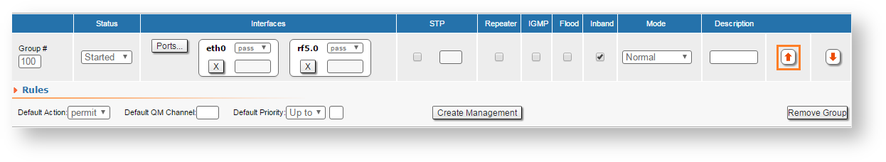
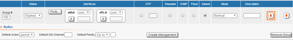
- Step 4
Move management switch group to the top using arrows on the right
| Center | |||||
|---|---|---|---|---|---|
|
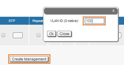
- Step 5
We have to create a VLAN interface and to assign it an ID. Let’s create VLAN 100 VLAN 100 interface by clicking the «Create Management» button and setting the ID 100:
| Center | |||||
|---|---|---|---|---|---|
|

| Note | ||
|---|---|---|
| ||
For tagged management choose the appropriate vlan tag for management traffic. For untagged management choose "0" tag value in case you don't need vlan management. |
...
In "Basic Settings" → "Network Settings" section set assign IP - address to the unit on auxiliary VLAN interface (don't forget about netmask).
| Note | ||
|---|---|---|
| ||
Please first remove the IP - address from "eth0" interface by just clicking the "X" box. |
You can leave factory IP-factory IP address on "eth0" interface in case it does not belong to any of your production network subnets. IP- IP address on "eth0" will remain local for wired Ethernet segment only.
| Center | |||||
|---|---|---|---|---|---|
|


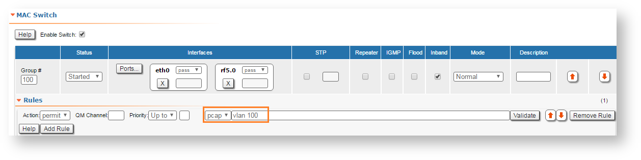
In "Basic Settings" → "MAC Switch" section, we can observe that a new rule has been created automatically for VLAN 100 VLAN 100 within Switch switch group 100:#100
| Center | |||||
|---|---|---|---|---|---|
|
For the data traffic, we have to create a separate Switch switch group.
- Step 6b (In case there is no need in VLAN tagged management interface)
In "Basic Settings" → "Network Settings" section set assign IP - address to the unit on SVI interface SVI interface (don't forget about netmask).
| Note | ||
|---|---|---|
| ||
Please first remove the IP - address from "eth0" interface by just clicking the "X" box. |
You can leave factory IP - address on "eth0" interface in case it does not belong to any of your production network subnets. IP - address on "eth0" will remain local for wired Ethernet segment only.
| Center | |||||
|---|---|---|---|---|---|
|
- Step 7 (Optional)
Set the default gateway IP - address
| Center | |||||
|---|---|---|---|---|---|
|
- Step 8
Before saving the current configuration, please make sure that you can access the unit on VLAN 100VLAN 100. If you connect the PC directly to the unit, you have to set VLAN 100 VLAN 100 for the outgoing traffic at the network interface.
...
| Center | |||||
|---|---|---|---|---|---|
|

| Note | ||
|---|---|---|
| ||
Read information at the "Apply, Test and Preview buttons for the configuration" section in order to find out the output of the «Apply», «Test» and «Preview» buttons for the new configuration performed. |
|
We have created switch group for management traffic, special interfaces for vlan management and we have set an IP - address to the vlan management interface. Now there should be connection to unit through VLAN 100.
We have to perform the same settings for the second unit and check the connectivity with VLAN 100 with VLAN 100 to each unit.
| Note | ||
|---|---|---|
| ||
If you have firmware software version "MINTv1.89.0" or lower please follow procedure described in the "Remote management of the R5000 units with firmware "MINTv1.89.0" or lower" section. |