...
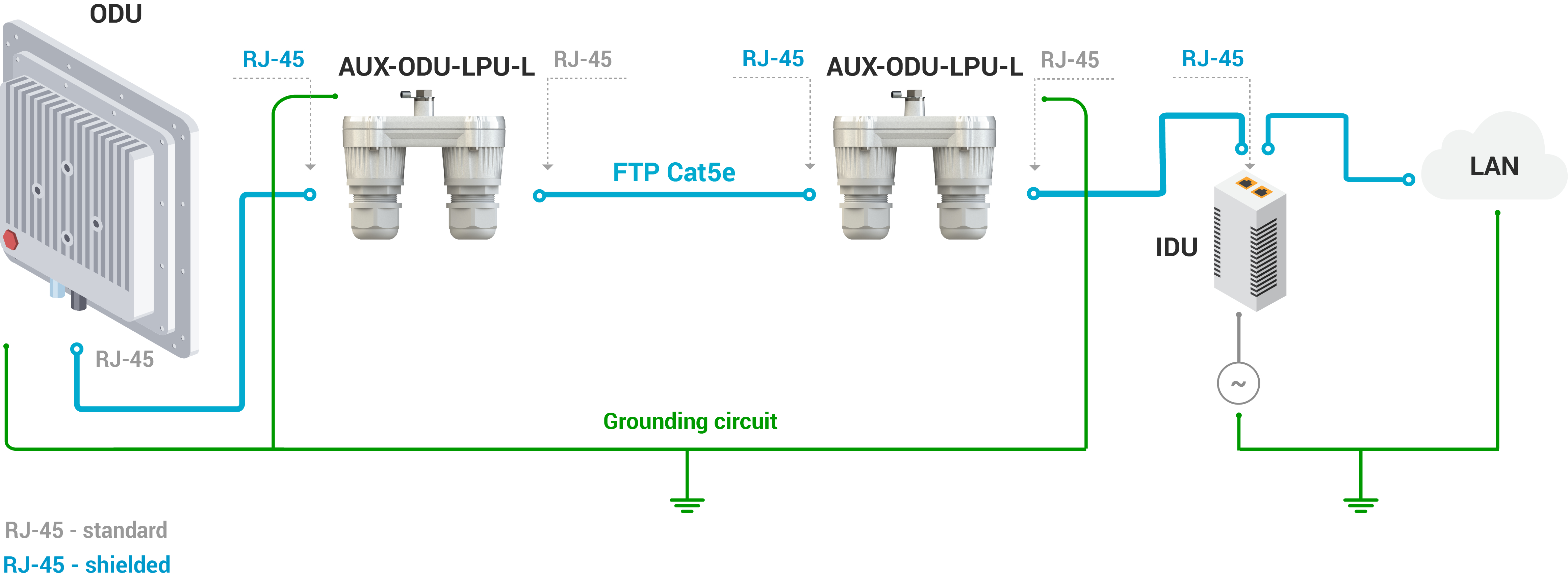
Make sure to install the two LPU devices as shown in the scheme below.
| Center |
|---|
| Scroll Title |
|---|
| title-alignment | center |
|---|
| title | Figure - Connection scheme |
|---|
| 
|
|
...
AUX-ODU-LPU-L is installed on a mast, using clamp. Attach the grounding cable (min cross-section 2.5 mm2) to the case, using grounding bolt.
| Center |
|---|
| scroll-title |
|---|
| title-alignment | center |
|---|
| title | Figure - AUX-ODU-LPU-L Mounting |
|---|
| | Gliffy Diagram |
|---|
| name | Aux-odu-lpu-l mounting |
|---|
| pagePin | 6 |
|---|
|
|
|
During AUX-ODU-LPU-L mounting it is necessary to provide a small loop of the FTP cable that should be below the cable gland. This ensures that water is not constantly channeled towards the connector. It will also serve as a cable compensation for the cable linear expansion as the temperature difference result.
| Center |
|---|
| scroll-title |
|---|
| title-alignment | center |
|---|
| title | Figure - Cable loop |
|---|
| | Gliffy Diagram |
|---|
| name | Aux-odu-lpu-l_loop |
|---|
| pagePin | 3 |
|---|
|
|
|
...
- Step 5: Insert the RJ-45 connector into the corresponding socket until you hear a click.
- Step 6: Screw the cable gland body into the port and tighten it. Do not apply excessive force.
- Step 7: Tighten the thread-lock sealing nut. Do not apply excessive force.
| Center |
|---|
| scroll-title |
|---|
| title-alignment | center |
|---|
| title | Figure - Cable gland assembly |
|---|
| | Gliffy Diagram |
|---|
| size | 950 |
|---|
| name | Aux-odu-lpu-l cable gland assy |
|---|
| pagePin | 5 |
|---|
|
|
|