...
Make sure to install the two LPU devices as shown in the scheme below.
| Center |
|---|
| Scroll Title |
|---|
| title-alignment | center |
|---|
| title | Figure - Connection scheme |
|---|
|
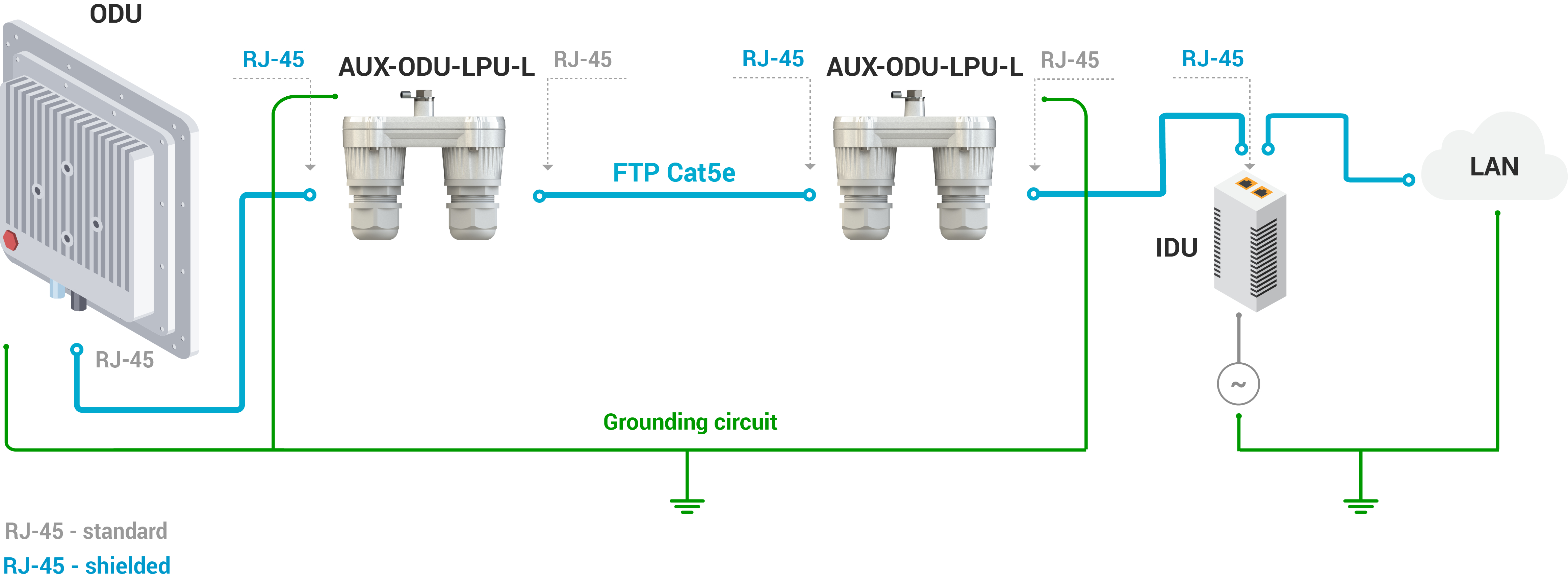 Image Modified Image Modified
|
| Warning |
|---|
|
Please note grounding cables should not be connected to the mast. All devices must use separate grounding cable that should be connected to the grounding circuit. The best scenario is when grounding cables are lined parallel to the Ethernet cable. |
...
AUX-ODU-LPU-L is installed on a mast, using clamp. Attach the grounding cable (min cross-section 2.5 mm2) to the case, using grounding bolt.
...
| Scroll Title |
|---|
| title-alignment | center |
|---|
| title | Figure - AUX-ODU-LPU-L Mounting |
|---|
|
| Gliffy Diagram |
|---|
| name | Aux-odu-lpu-l mounting |
|---|
| pagePin | 6 |
|---|
|
|
During AUX-ODU-LPU-L mounting it is necessary to provide a small loop of the FTP cable that should be below the cable gland. This ensures that water is not constantly channeled towards the connector. It It will also serve as a cable compensation for the cable the cable linear expansion as the temperature difference result.
...
| Scroll Title |
|---|
| title-alignment | center |
|---|
| title | Figure - Cable loop |
|---|
|
| Gliffy Diagram |
|---|
| name | Aux-odu-lpu-l_loop |
|---|
| pagePin | 3 |
|---|
|
|
| Warning |
|---|
|
Missing or bad grounding may leave the unit vulnerable to lightning damage. |
...
- Step 5: Insert the RJ-45 connector into the corresponding socket until you hear a click.
- Step 6: Screw the cable gland body into the port and tighten it. Do not apply excessive force.
- Step 7: Tighten the thread-lock sealing nut. Do not apply excessive force.
...
| Scroll Title |
|---|
| title-alignment | center |
|---|
| title | Figure - Cable gland assembly |
|---|
|
| Gliffy Diagram |
|---|
| size | 950 |
|---|
| name | Aux-odu-lpu-l cable gland assy |
|---|
| pagePin | 5 |
|---|
|
|