...
In the "Wired interface" tab, the Ethernet interface status can be monitored, as well as duplex mode and traffic load for reception and transmission. The wired interface statistic is available on the right side, it can be reset by the "Clear counters" button.
| Center |
|---|
| Scroll Title |
|---|
| title-alignment | center |
|---|
| title | Figure - Wired interface paraqmeters |
|---|
|
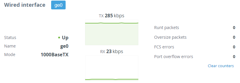 Image Modified Image Modified
|
| Center |
|---|
| Parameter | Description |
|---|
| Runt packets | Packets less than 64 bytes in size | | Oversize packets | Packets larger than 9038 bytes | | FCS errors | Packets dropped due to checksum mismatch. The possible reasons for the error counter increasement are described in the "Troubleshooting" article | | Port overflow errors | Packets dropped due to port buffer overflow |
|
...
The “Radio” tab displays the current settings of the wireless connection, as well as the link load in the uplink and downlink directions.
...
| Scroll Title |
|---|
| title-alignment | center |
|---|
| title | Figure - Wireless link parameters |
|---|
|
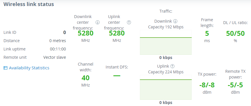 Image Modified Image Modified
|
| Center |
|---|
| Parameter | Description |
|---|
| Link ID | Wireless link can be established only with devices which have the same link ID. | | Distance | The estimated link length. | | Link uptime | The link operating time since the last outage. | | Remote unit | The remote device name. | | Center frequency | The downlink and uplink center frequency value set in the "Radio" section manually or by the automatic frequency selection mechanism. | | Channel width | The channel width value set in the "Radio". | | Instant DFS | Instant DFS option state (only for Quanta 5 family devices). | | Traffic | The wireless link capacity and utilization in the uplink and downlink directions. | | Frame size | The frame size value set in the "Radio". | | DL / UL ratio | The ratio of the downlink traffic to uplink, set in the "Radio" section manually or by a mechanism for automatically determining the optimal ratio. | | Tx power | The transmitter power value on the local device determined by the automatic power control mechanism for each polarization. If the automatic transmit power control tool is disabled, the value set manually by the user will be displayed. | | Remote X power | The transmitter power value on the remote device determined by the automatic power control mechanism for each polarization. If the automatic transmit power control tool is disabled, the value set manually by the user will be displayed. |
|
...
- The overall wireless link availability since the last device reboot, the number of wireless outages when the connection was unavailable.
- Availability statistics for each modulation, for both polarization for downlink and uplink streams.
...
| Scroll Title |
|---|
| title-alignment | center |
|---|
| title | Figure - Availability statistics |
|---|
|
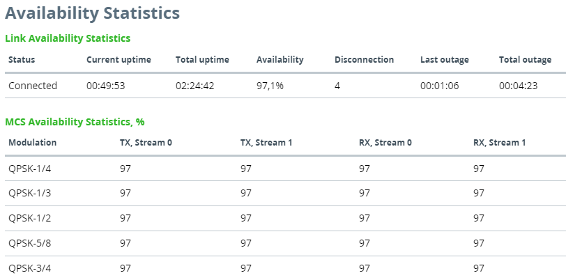 Image Modified Image Modified
|
Modulation code scheme
Modulation and coding schemes are selected independently for each channel (uplink and downlink) for both polarizations. Current modulation for each channel is displayed in the MCS subsection.
...