| Hide_comments |
|---|
| Scroll Ignore | |
|---|---|
|
Cable Gland Assembly
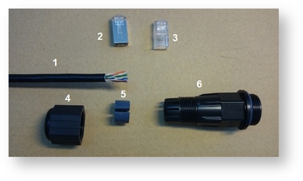
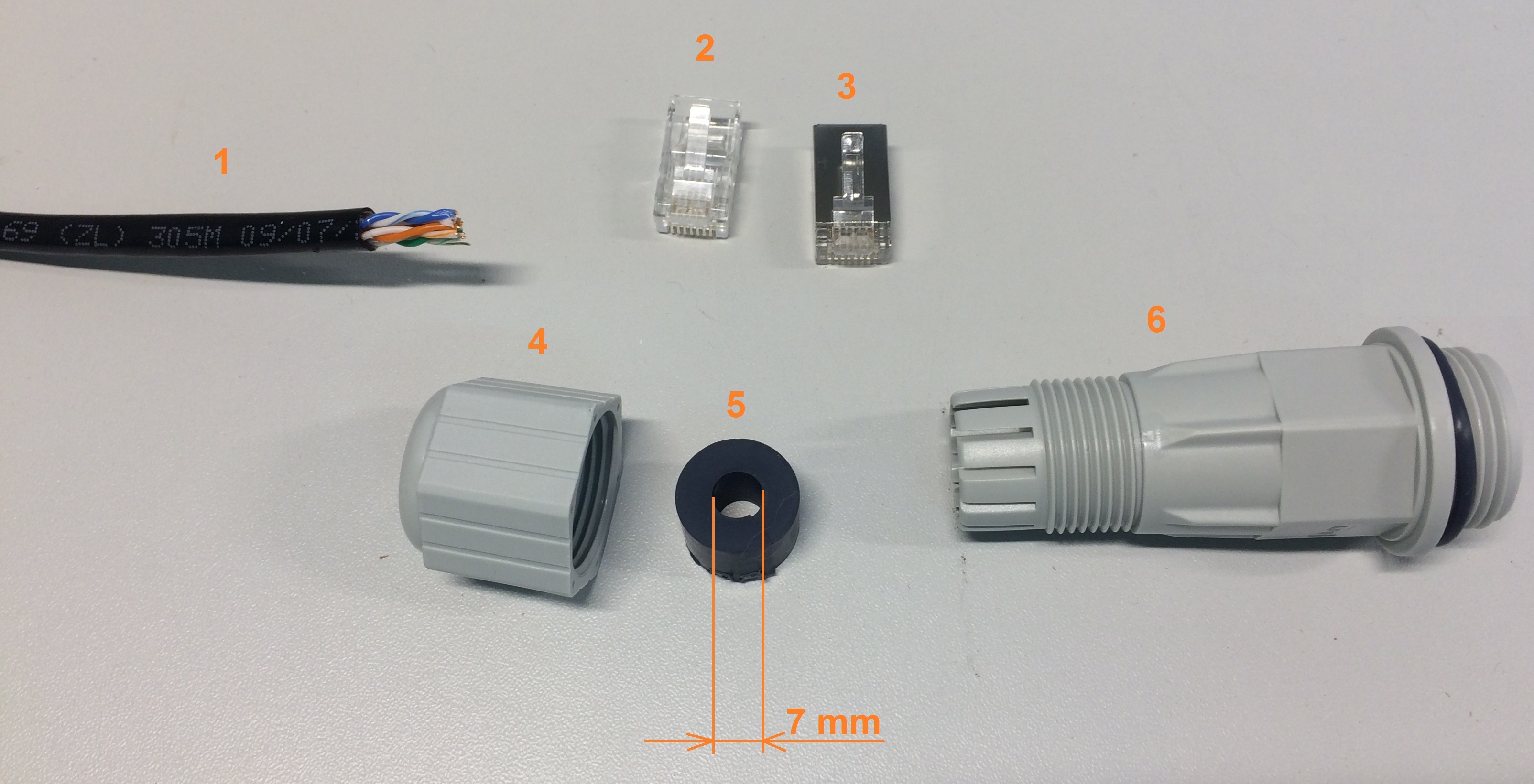
Required components:
- FTP cable category 5e
- Shielded Unshielded RJ-45 connector;Unshielded
- Shielded RJ-45 connector;
- Cable gland nut;
- Split sealing grommet;
- Cable gland threaded coupling.
| Note |
|---|
| |
| |
Cable gland can be assembled on pre-crimped cable. |
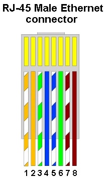
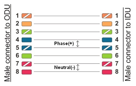

- Crimp the unshielded RJ-45 connector (32) onto the cable using the crimping tool.
Pin-out scheme: T568B wiring standards
| Note | ||
|---|---|---|
| ||
Do not use the shielded RJ-45 connector on this end of the cable as it should be attached on the IDU end. |
| Warning | ||
|---|---|---|
| ||
MAKE SURE THAT THE RJ-45 CONNECTOR IS WELL-CRIMPED. A LOOSE CONNECTOR CAN DAMAGE THE DEVICE. PLEASE NOTE THAT SUCH DAMAGE IS NOT COVERED BY THE WARRANTY. |
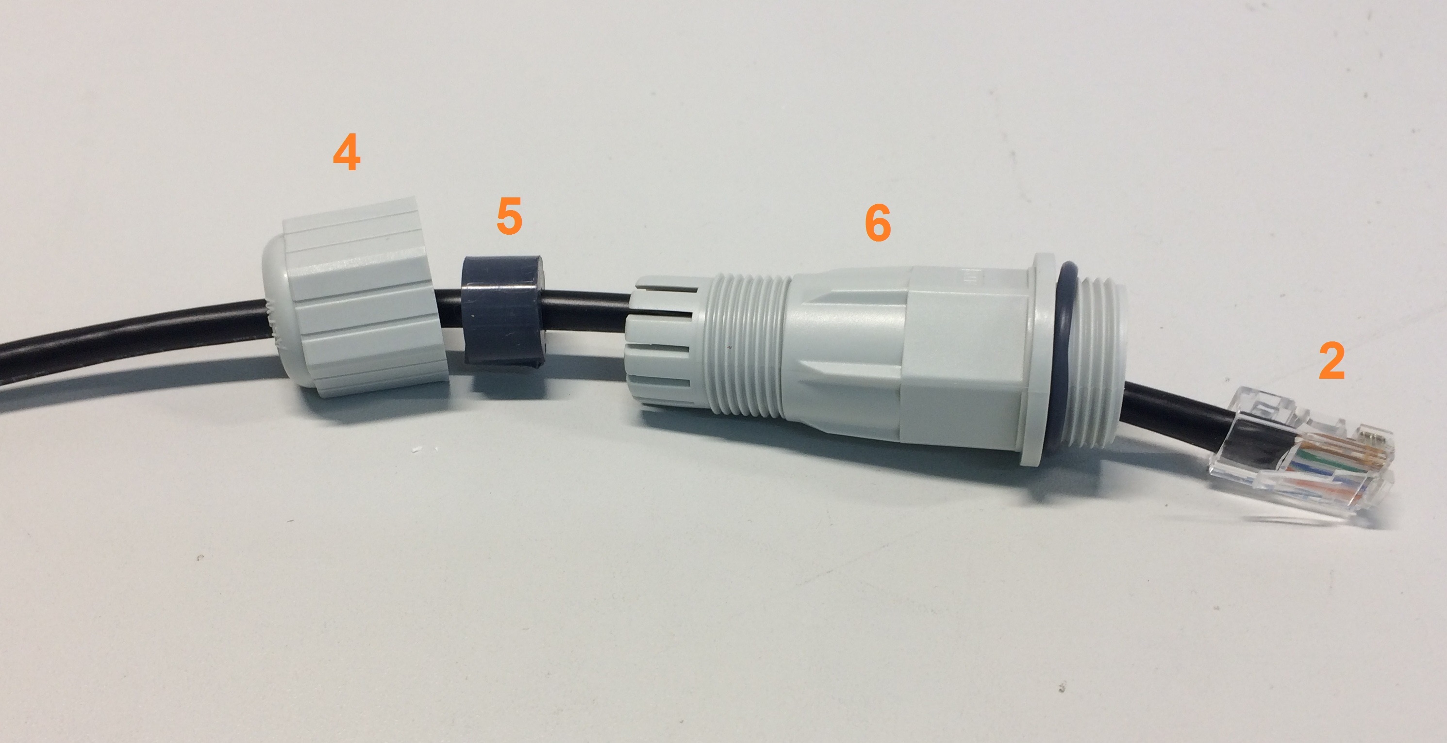
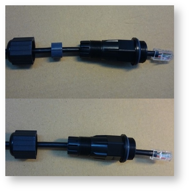
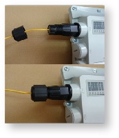
- Put the cable gland nut (4), the split sealing grommet (5) and the cable gland threaded coupling (6) onto the pre-terminated cable.
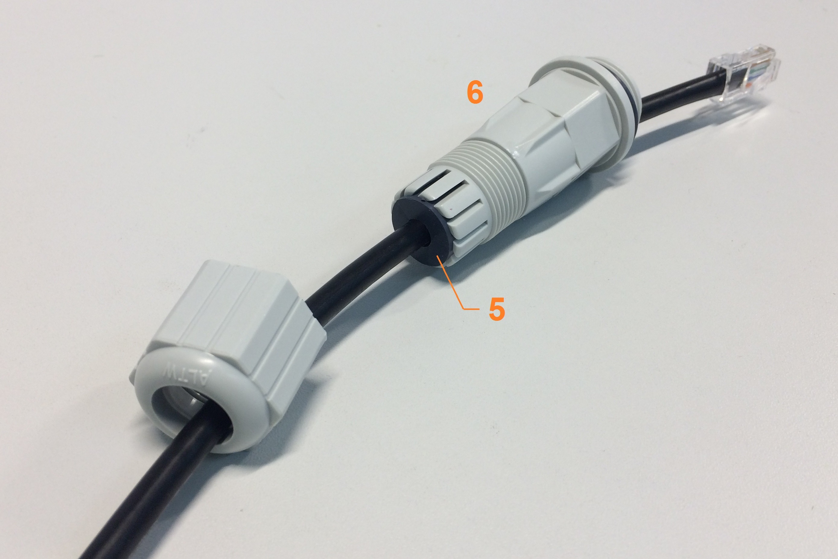
- Insert the split sealing grommet (5) into the cable gland threaded coupling (6).
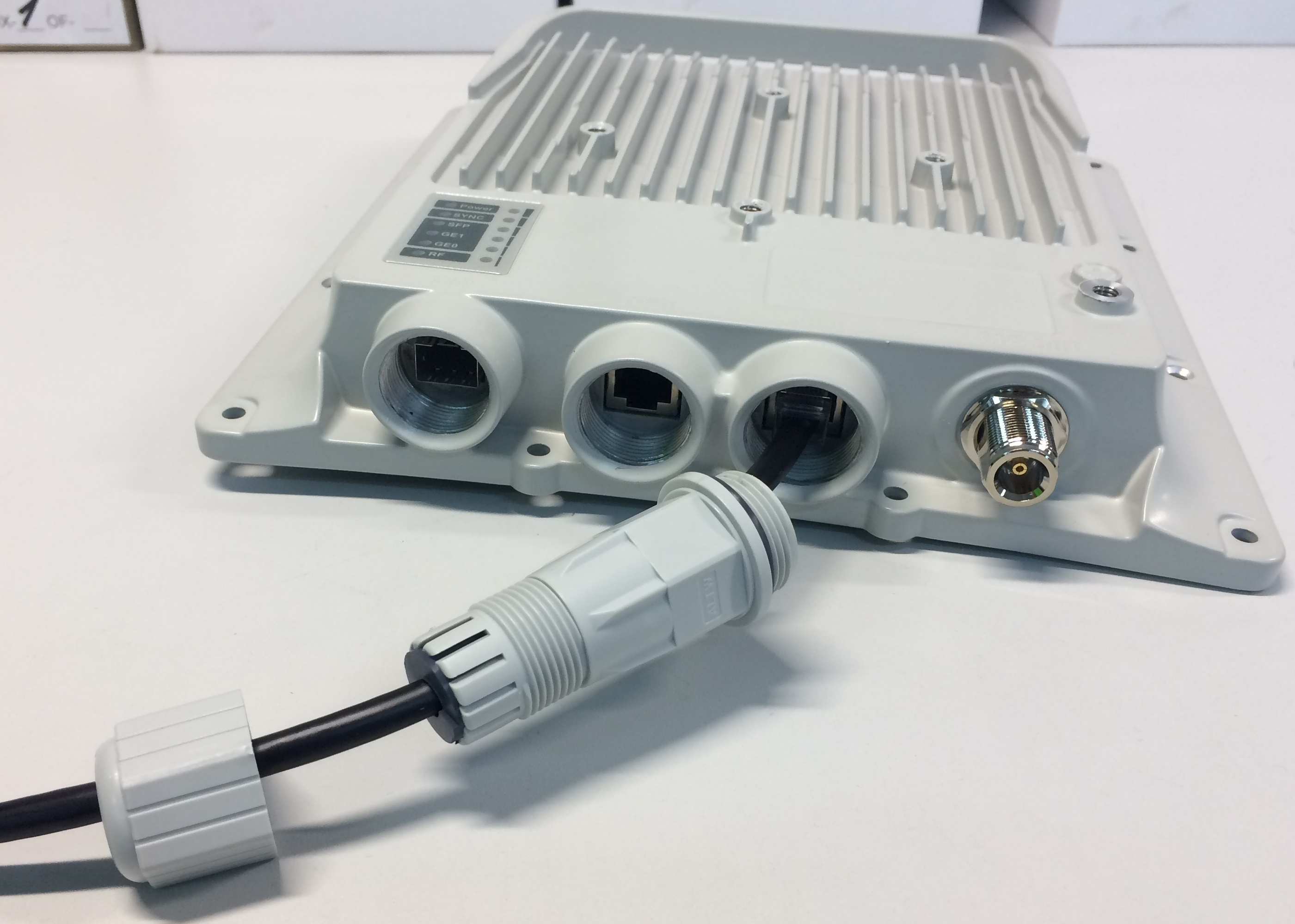
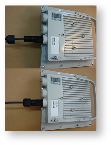
- Insert the connector into the socket until you hear a click.
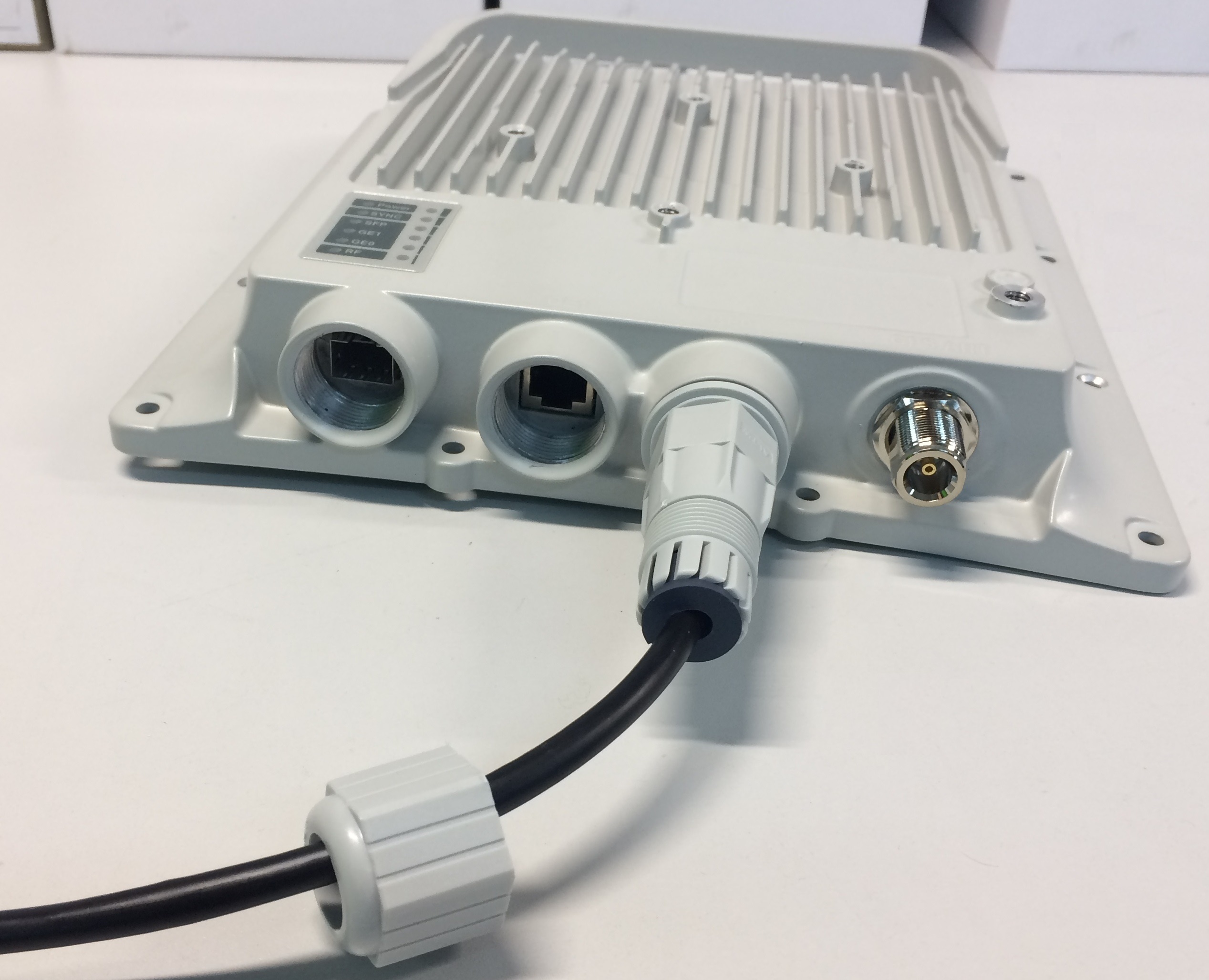
- Screw the cable gland threaded coupling (6) into the port and tighten it.
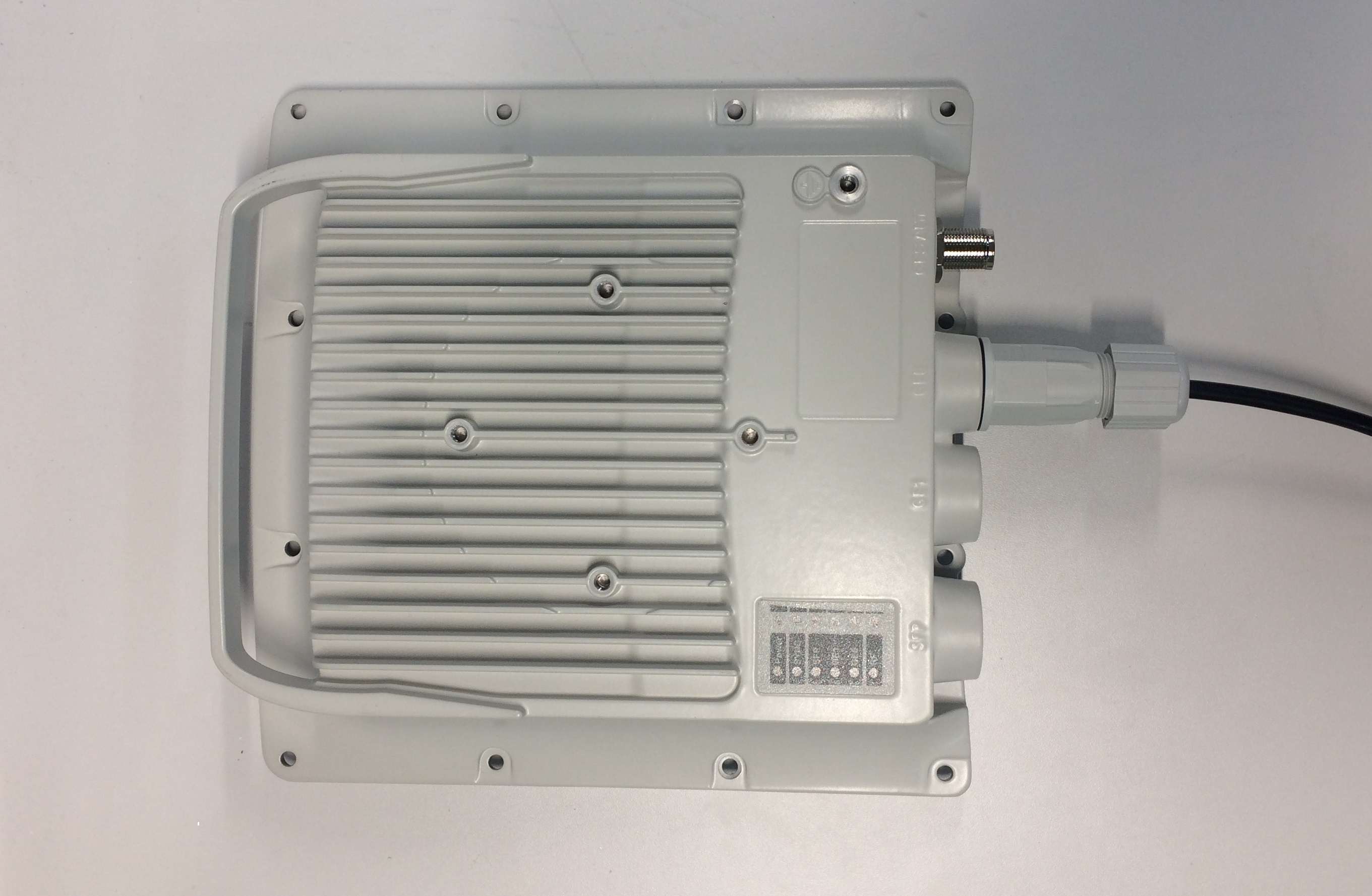
- Tighten the cable gland nut (4). Do not apply excessive force.
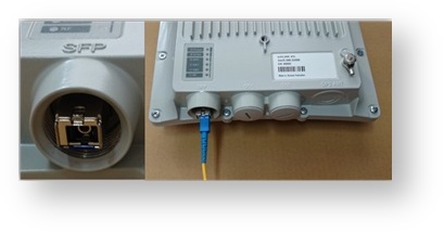
Cable Gland Assembly for Optical Cable
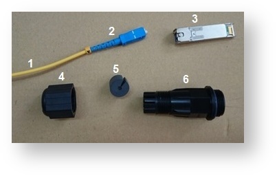
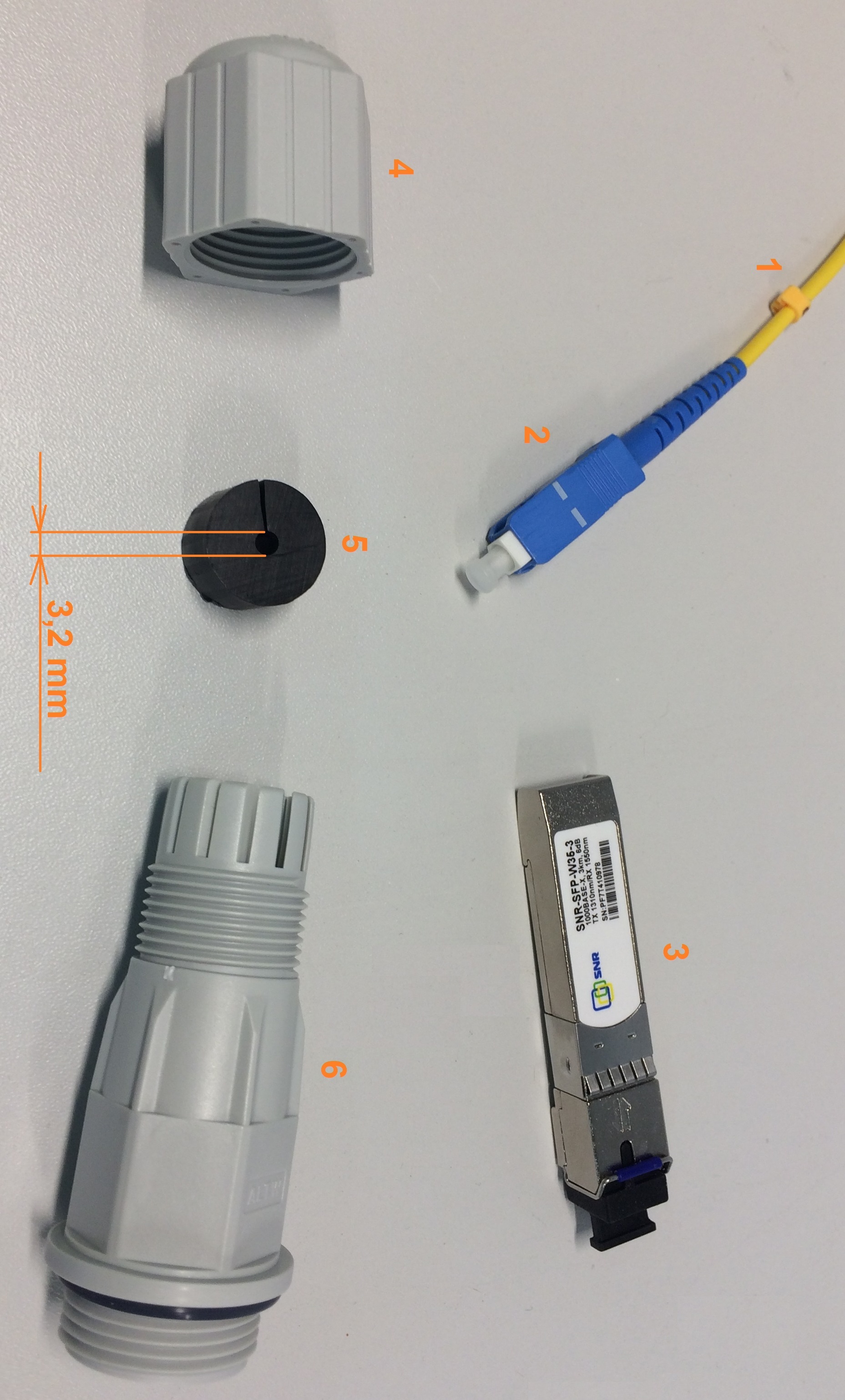
Required components:
- Optical cable
- Optical connector
- SFP-module
- Cable gland nut
- Split sealing grommet
- Cable gland threaded coupling.
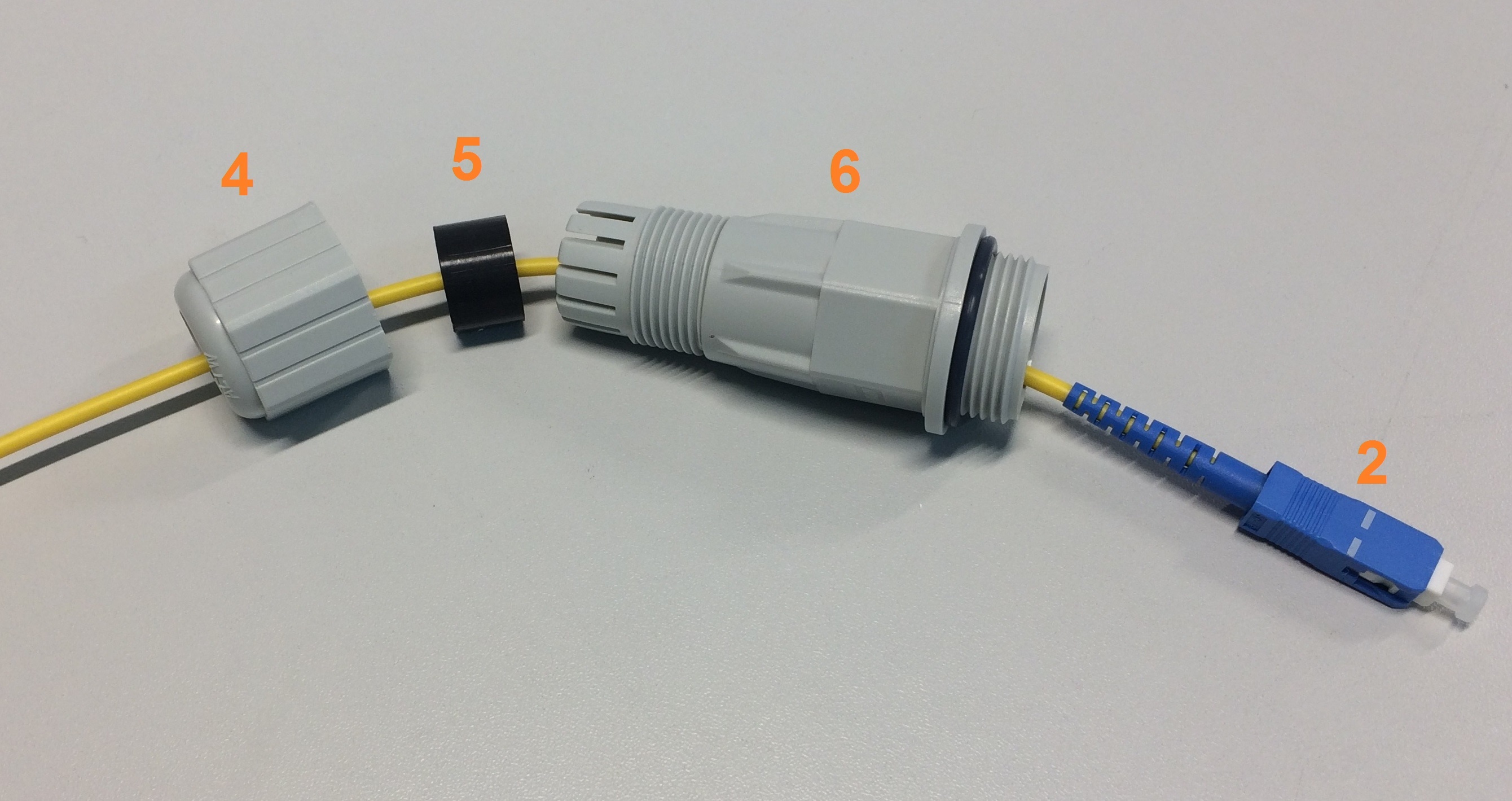
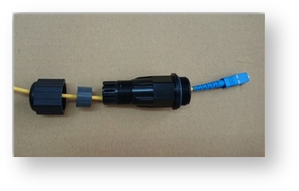
- Put the cable gland nut (4), the split sealing grommet (5) and cable gland threaded coupling (6) onto the pre-terminated optical cable (1).
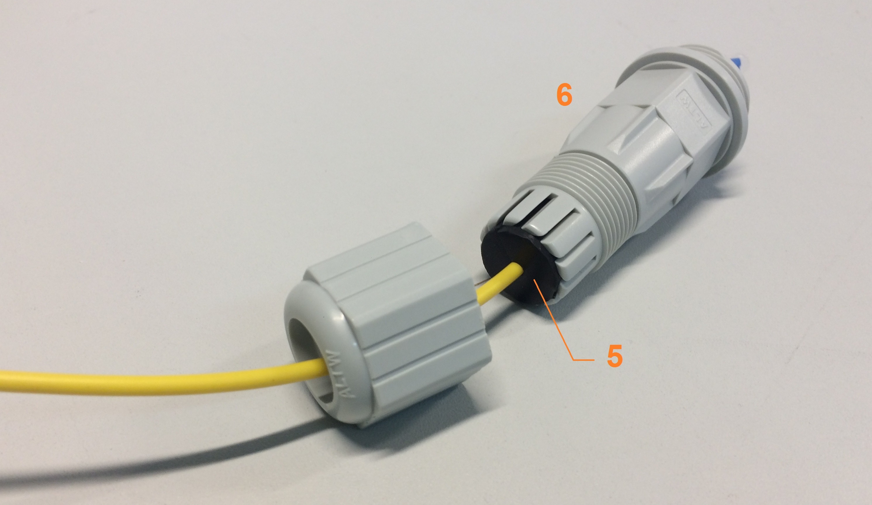
- Insert the split sealing grommet (5) into the cable gland threaded coupling (6).
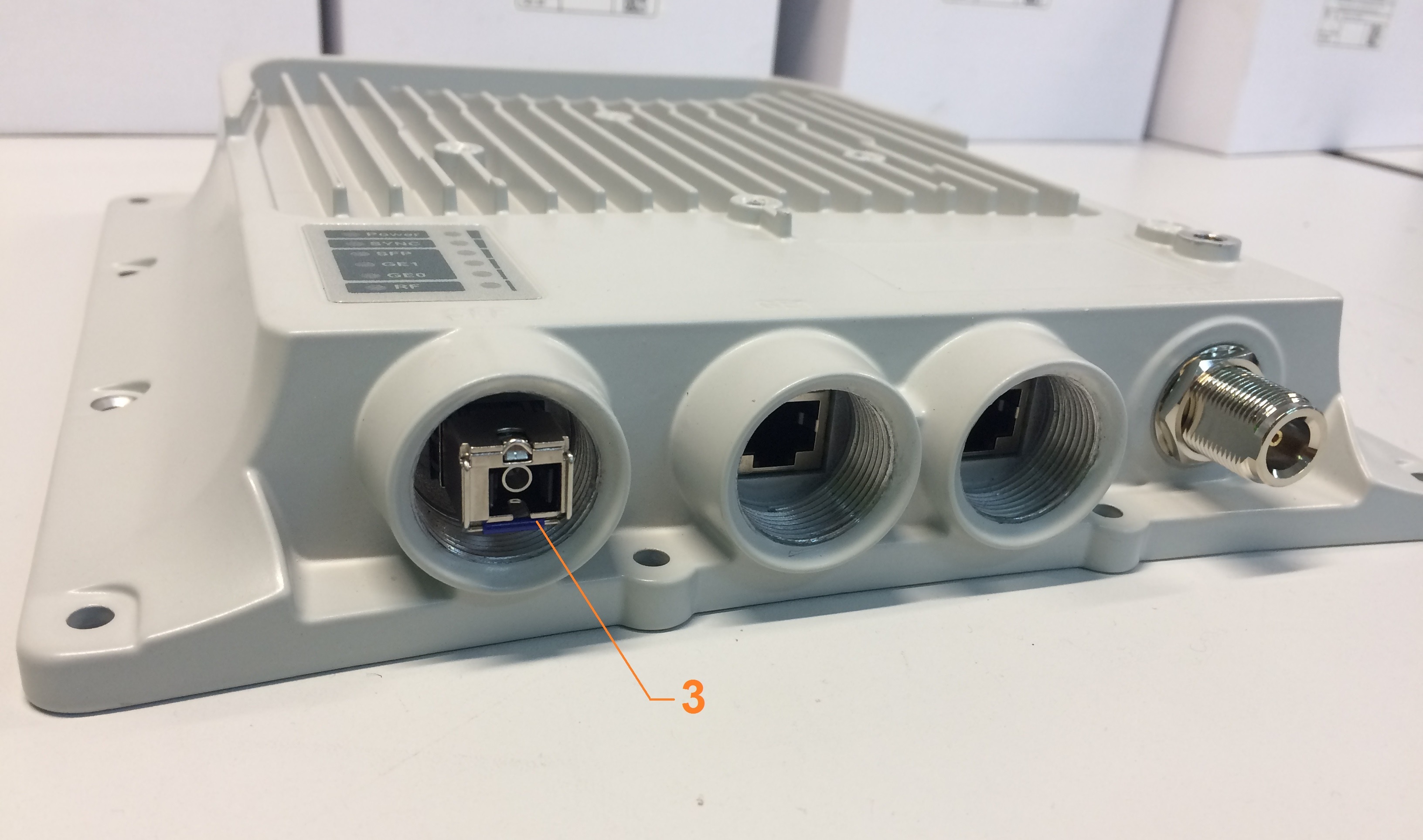
- Set the SFP-module (3) into the socket until you hear a click.
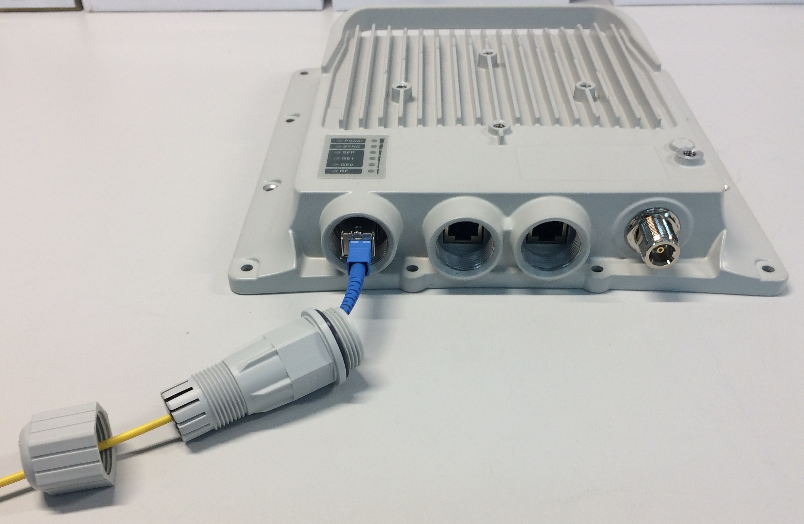
- Insert the optical connector into the SFP-module (3).
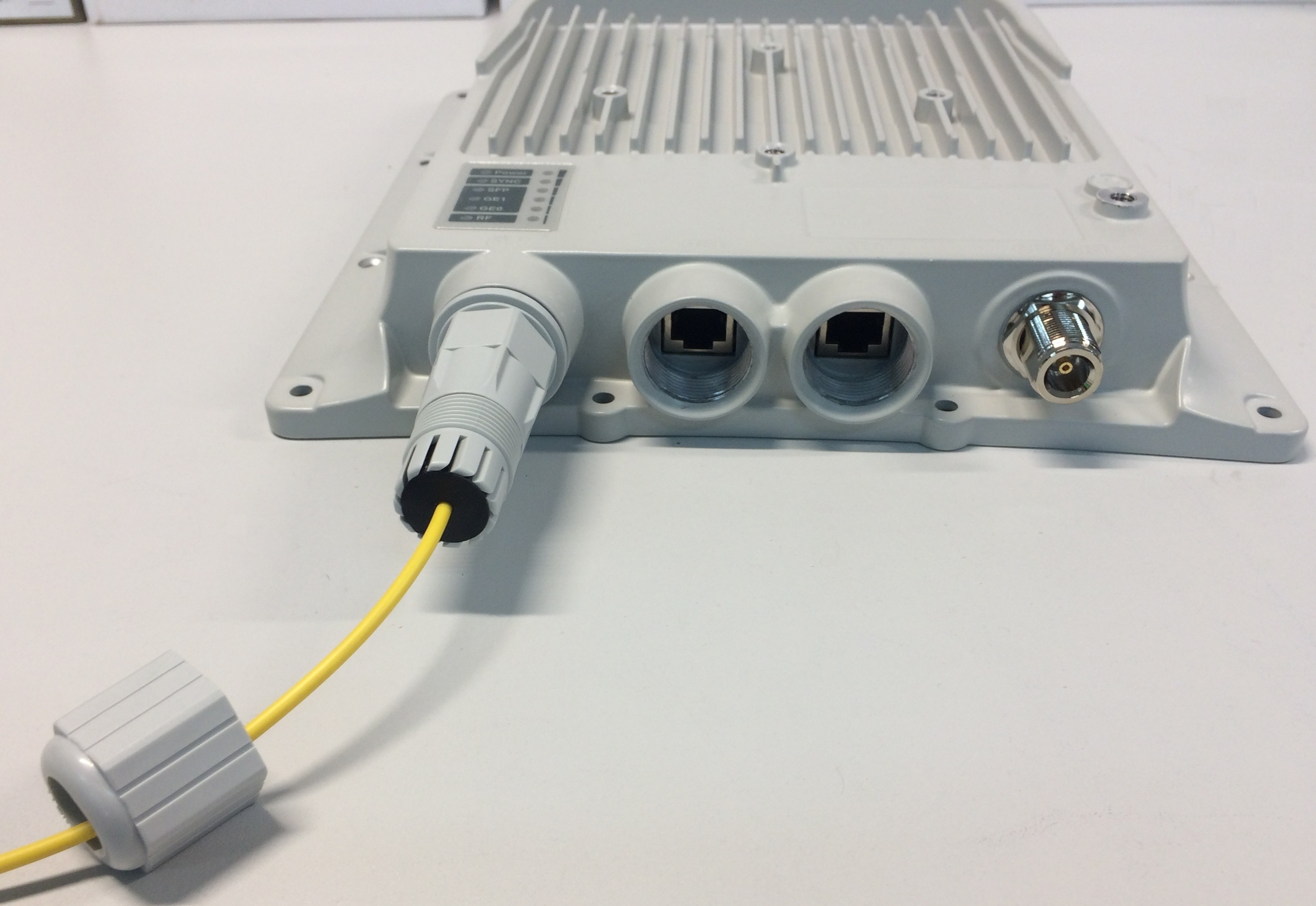
- Screw the cable gland threaded coupling (6) into the port and tighten it.
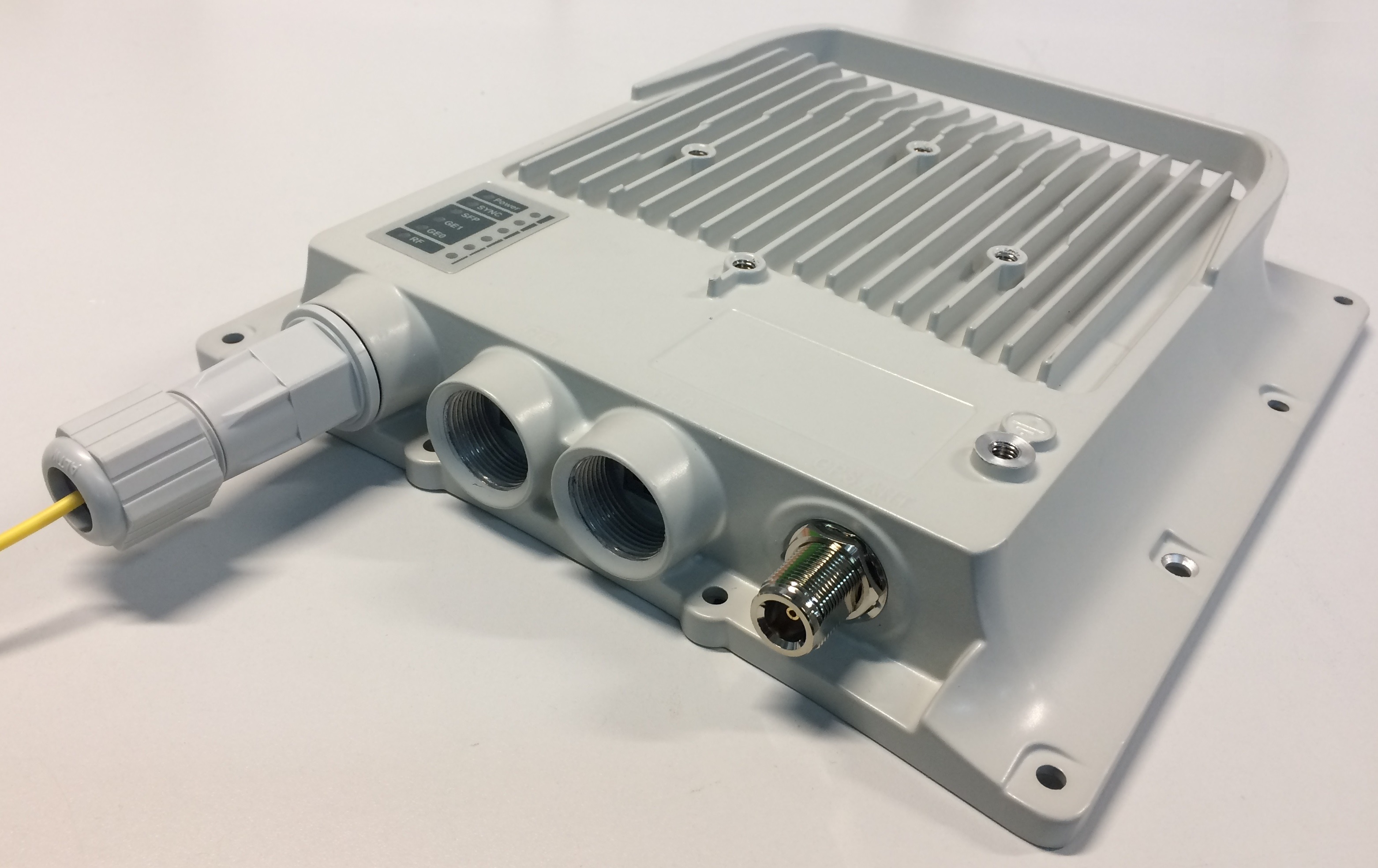
- Tighten the cable gland nut (4). Do not apply excessive force.
| Note | ||
|---|---|---|
| ||
In order to disassemble SFP, please disconnect the optical cable, pull the clip of the SFP-module and withdraw the SFP-module from the slot. |