...
This part of the article contains routing configuration scenarios for various tasks. In order to focus on the static routing topic, let's make the following assumptions, which are valid for all scenarios:
- the radio links are established between the wireless devices;
- at the endpoint devices (the PCs), the IP addresses of the wireless devices to which they are directly connected are set as gateway. After specifying the gateway, each endpoint devices device adds a default route to its routing table;
- switching is off on the devices of the InfiLINK 2x2 and InfiMAN 2x2 families;
- in the examples for the InfiLINK 2x2 and InfiMAN 2x2 families of devices, the IP addresses are assigned to the physical interfaces, however, virtual interfaces can be used instead, for example, vlan interfaces.
...
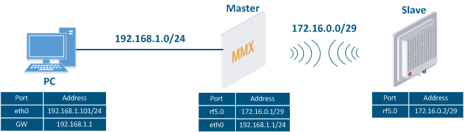
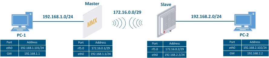
Let's look at the task concerning the routing configuration for the management traffic (Figure 1). For this task, the Slave's device management interface must be accessible to the engineer working at the PC, while . Since the PC and the Slave devices belong to different subnets, routing must be used.
| Center |
|---|
Figure 1 - Scheme of Routing configuration for the management traffic routing configuration for using the InfiLINK 2x2 / InfiMAN 2x2 families of devices |
...
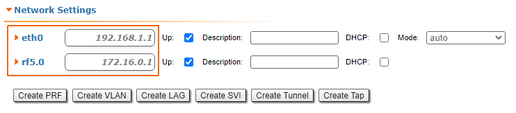
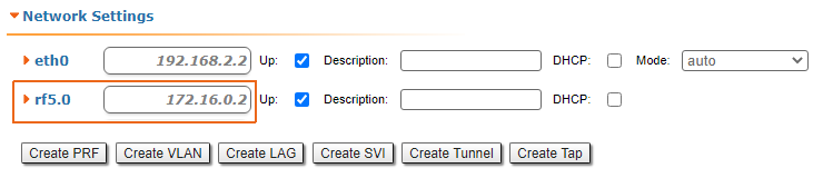
| Description | Add the IP addresses to device's interfaces the interfaces of the devices according to the scheme. |
|---|---|
| Master |
|
| Slave |
|
...
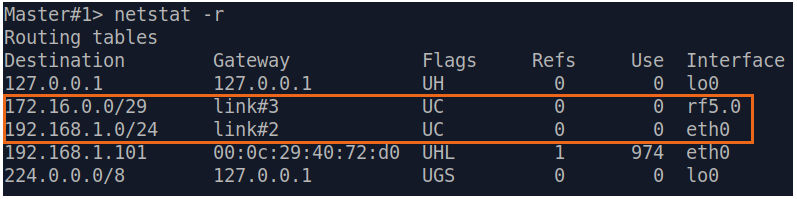
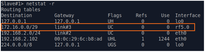
| Description | Analyze the routing table: after adding the IP addresses to the device's interfaces, the routing table was filled up with entries for every new connected network (mark marked as C). |
|---|---|
| Master |
|
| Slave |
|
Step 3
| Description | Add static routes for the connection between the PC and the Slave. |
|---|---|
| Master | The Master device is intermediate on the path of the packets between the PC and the Slave. Routes towards the PC and towards the Slave have been added to the Master's device routing table based on the configuration in the previous steps (see step 2), so there is no need to add static entries at the Master device. |
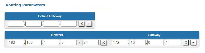
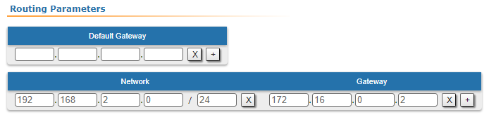
| Slave | A static route must be added towards PC1's network:
|
...
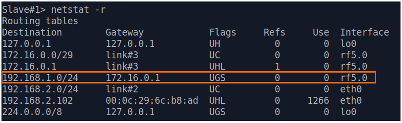
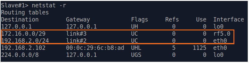
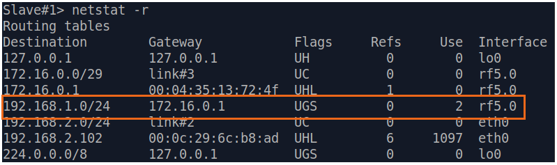
| Description | Analyze the routing table: a static entry (marked with as S) has been added to the Slave's routing table. |
|---|---|
| Master | see step 2 |
| Slave |
|
...
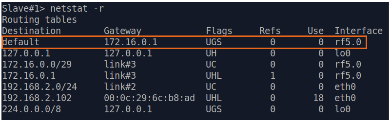
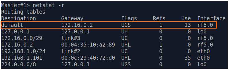
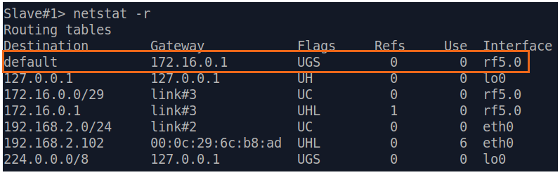
| Description | If a default route has been added as in step 3a, a corresponding entry (marked with as S) will be added to the routing table. |
|---|---|
| Master | see step 2 |
| Slave |
|
...
Let's look at the task of performing the routing configuration for the data traffic using a PtP scheme (Figure 2). For this task, the connectivity between the PC-1 and the PC-2 devices should be established using routing, as PC-1 and PC-2 belong to different subnets.
| Center |
|---|
Figure 2 - Scheme of Routing configuration for the data traffic routing configuration for using the InfiLINK 2x2 / InfiMAN 2x2 families of devices |
...
| Description | Analyze the routing table: after adding IP addresses to the devices' interfaces, the routing tables were filled up with entries specifying the directly connected networks (markmarked as C). |
|---|---|
| Master |
|
| Slave |
|
Step 3
| Description | Add static routes for the connection between PC-1 and PC-2. There is no route towards the PC-2's subnet on the Master device, and no route towards the PC-1's subnet on the Slave. Let's add these routes. |
|---|---|
| Master |
|
| Slave |
|
...
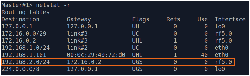
| Description | Analyze the routing table: a static entry (marked with as S) has been added to the routing tables of the Master 's and to the Slave 's devices routing tables. |
|---|---|
| Master |
|
| Slave |
|
Step 4a
| Description | If a default route has been added in step 3a, a corresponding entry (marked with as S) will be added to the routing tables. |
|---|---|
| Master |
|
| Slave |
|
...
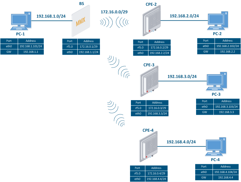
Let's look at the task of performing the routing configuration for the data traffic using a PtMP scheme (Figure 3). With this task, the The connectivity between PC-1, PC-2, PC-3 and PC-4 should be established using routing, since all the PCs belong to different subnets.
| Center |
|---|
Figure 3 - Scheme of Routing configuration for the data traffic routing configuration for using the InfiLINK 2x2 / InfiMAN 2x2 families of devices |
...