| Gliffy Diagram |
|---|
| name | Схема ERC Evolution |
|---|
| pagePin | 1 |
|---|
|
| Gliffy Diagram |
|---|
| name | indicators panel Copy |
|---|
| pagePin | 1 |
|---|
|
| Gliffy Diagram |
|---|
| name | InfiMAN Evolution Indication |
|---|
| pagePin | 1 |
|---|
|
...
LED indicators on the InfiMAN Evolution family base station sectors are located in the the cable glands ports. These indicators help to monitor the device's status during the installation. The correspondence between the state of the indicators and the current device state is shown in the table below.
| Center |
|---|
| scroll-title |
|---|
| title-alignment | center |
|---|
| title | Figure - LED indication of R5000-Mmx, R5000-Qmx, R500-Omx devicesInfiMAN Evolution BS |
|---|
| | Gliffy Diagram |
|---|
| name | Индикация H08 Copy | InfiMAN Evolution Indication |
|---|
| pagePin | 1 |
|---|
|
|
|
| Center |
|---|
| Scroll Title |
|---|
| title-alignment | center |
|---|
| title | Table - LEDs modes and device status of R5000-Qmxb, R5000-Mmx and R5000-Omx modelsInfiMAN Evoluton BS |
|---|
| | LED | State | Status | Description |
|---|
Gigabit Ethernet SFP | Flash | Initialization | The LEDs on both ports light up with white on second. Then LEDs check is performed: red, blue, green are lightened up sequentially. |
|---|
| Flash | Loading | Only for Gigabit Ethernet port: at the beginning green is lightened a few seconds, on the second loading stage switches to blue. | | ON/Blue | Power | Only for Gigabit Ethernet port. | | ON/Red | Speed 10 Mbps | Only for Gigabit Ethernet port. | | ON/Yellow | Speed 100 Mbps | Only for Gigabit Ethernet port. | | ON/Green | Speed 1000 Mbps |
| | ON/Green | ERConsole stage | Port with the established link lights up with green, the second port remains blue. |
|
|
...
InfiMAN Evolution ST and InfiLINK Evolution devices have a LED indicator set located at the back of each device, displaying the current device state.
| Center |
|---|
| Scroll Title |
|---|
| title-alignment | center |
|---|
| title | Figure - LED indication of R5000-Smn, R5000-Lmn devicesInfiMAN Evoluton ST, InfiLINK Evolution |
|---|
| | Gliffy Diagram |
|---|
| name | H11 индикация indicators panel Copy |
|---|
| pagePin | 1 |
|---|
|
|
|
PWR - power indicators will light red when the device is connected to a power source, yellow when 10/100 Mbps wired connection appears and green when 1000 Mbps wired connection appears. Other indicators are used to perform coarse antenna alignment. The more indicators are on, the better wireless connection is established. The blinking indicator means an intermediate state. The more often the indicator blinks the higher level connection is established.
...
The factory reset process using the ERConsole is described in the "Emergence Repair Console" article.
| Center |
|---|
| Scroll Title |
|---|
| title-alignment | center |
|---|
| title | Figure - The recommended connection scheme |
|---|
| | Gliffy Diagram |
|---|
| name | Схема ERC R5000 CopyEvolution |
|---|
| pagePin | 2 |
|---|
|
|
|
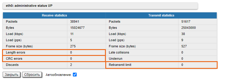
Checking the status of the Ethernet interface
...
If you were able to access the device by connecting directly, try to determine the possible reason for the unavailability through the network. Pay attention to the wired interface statistics. In order to do this, go to the "Device status" section of the web interface and open the "General statistics" window for the Ethernet interface in the "Interface statistics" section. Pay attention to the CRC errors number, as they indicate a violation of the data integrity during the transmission over the wired segment. Also, the problem can be caused by a queue overflow (Retransmit limit) or an inappropriate frame size (Out of rangeLength errors).
| Center |
|---|
| Scroll Title |
|---|
| title-alignment | center |
|---|
| title | Figure - Interface statistics |
|---|
| 
|
|
...
Pay attention to the duplex mode on the network devices connected to the wireless router. This information is available in the the web interface. Proceed to the "Device status" section - "Interface statistics" and open the "General statistic" for the Ethernet interface, or run the "ifconfig eth0" command in the command line interface.
| Center |
|---|
| Scroll Title |
|---|
| title-alignment | center |
|---|
| title | Figure - Duplex mode |
|---|
|  Image Removed Image Removed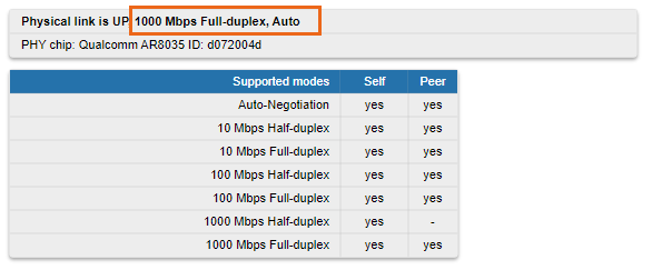 Image Added Image Added |
|
We recommend to set the auto-negotiation mode provided by the Ethernet standard. The problem can occur due to the connection between two devices with different duplex settings. For example, if one device is in auto-negotiation mode and the other is in fixed full duplex mode.