...
...
#1> ifc radio {up | down}
...
#1> xg [arguments]
| Code Block |
|---|
|
#1> xg
usage:

   xg -type {master | slave}
Radio frame params relatedconfig
   xg config -peer-exported
   xg config -defaults
   xg config -tddmake-sync-src {freerun | gnss}release-defaults

   xg -dlquota {1..99/1}[-grids-carrier-ix=<carrier-ix>] [-grids-band=<channel-width>] -grids {<freq_start>[-<freq_end>[/<step>]]}[,...]
   xg -sframelen {1 | 2 | 5 | 10[-grids-carrier-ix=<carrier-ix>] [-grids-band=<channel-width>] -grids=

 General settings
   xg -type {master, slave}
   xg -tdd-maxsync-distancesrc {0..120000/1} freerun, gnss}

 Link shared settings (Radio Front End)
   xg -cell-id {0..15/1}
Radio front end related
   xg -freqchannel-dlwidth {10, 20, 40}
   (channel-width== 10:4905): xg -freq-dl {6005..5995/10 | 6415/50}
   (channel-width== 20):4910..5990/10 | channel-width==40:4920..5980 xg -freq-dl {6010..6410/20}
   (channel-width 40): xg -freq-uldl {channel-width==10:49056020..5995/10 | 6400/50}
   (channel-width==20:4910..5990/10 | channel-width==40:4920..5980/20}
   xg -txpwr {0..27/1 10): xg -freq-ul {6005..6415/50}
   (channel-width 20): xg -channelfreq-widthul {10 | 20 | 40}

Modulation related
   xg -amc-strategy {normal | conservative | aggressive}6010..6410/20}
   (channel-width 40): xg -freq-ul {6020..6400/50}

 Link shared settings (Frame Config)
   xg -max-mcsdistance {1..10100/1}

DFS/RSSI scan/Radar detection

Ethernet datapath related    xg -sframelen {2, 4, 5, 10}
   xg -qos-strategy {normal | conservative | aggressive | off}

Supplementary

alias:
   xg -freq <val> => xg -freq-dl <val> -freq-ul <val>

dlquota {1..99/1}

 RF per-station settings
   xg -txpwr {0..27/1}
   xg -appendconfctrl-v2-startblock-boost {0, 1}

 Modulation related
   xg -appendconfamc-v2strategy <encoded web config>{normal, conservative, aggressive}
   xg -appendconf-v2-end
   xg [-grids-carrier-ix=<grids-carrier-ix>] [-grids-band=<grids-band>] -grids {<freq_start>[-<freq_end>[/<step>]],...}max-mcs {1..10/1}

 DFS/RSSI scan/Radar detection
   xg [-grids-carrier-ix=<grids-carrier-ix>] [-grids-band=<grids-band>] -grids=freq-auto {0, 1}

 Ethernet  xg stat [-phy] [-1]datapath related
   xg stat -clear
   xg capabilities

-traffic-prioritization {off, on}

 Supplementary

 aliases:
   xg config
-freq <val> => xg config -self
   xg config -peer-exported
xg config -defaults |
Command arguments
Point-to-point link can be set between a Master and a Slave unit only. In order to choose InfiLINK XG device type, use the command:
- xg -type {master | slave}
Example:
| Code Block |
|---|
-freq-dl <val> -freq-ul <val> |
"xg" command arguments description is given in the table below
Example:| Center |
|---|
| Scroll Title |
|---|
| title | Table - "xg" arguments description |
|---|
| | Command | Description |
|---|
| xg config | - View the configuration of the local unit
| | xg config -peer-exported | The outputs have the following view: |
|
type master
|
In order to setup TDD synchronization parameters, use the command:
- xg -tdd-sync-src {freerun | gnss}
- "freerun" - unsynchronized frame start.
- "gnss" - synchronization from built-in GPS/GLONASS receiver.
| Warning |
|---|
|
GNSS option is effective for Master unit only. |
| Warning |
|---|
|
Before enabling gnss option make sure that built-in GNSS-receiver is configured properly. Use "gps" command to configure or check the status (use values of "HDOP" up to 1.5) |
Possibility of the frequency re-use depends on the antenna types, placement, direction, link distances, etc.
| Warning |
|---|
|
Please note that the following settings must be equal for the co-located units: - All co-located units must be Masters
- Downlink/uplink ratio
- Air frame period
- Maximal distance
- Channel width
|
If you need to set a downlink/uplink ratio, use the following command, specifying as a value the size of downlink subframe relative to the whole frame (e.g. “xg -dlquota 70” should be specified for downlink/uplink ratio of 70/30):
Actual downlink/uplink ratio might be different due to internal system limitations. The system chooses closest available ratio automatically. The current value of this ratio can be checked in the output of "xg capabilities" command.
v3-start
xg -v3 <encoded web config>
xg -v3-end |
| | xg config -defaults | - View the default configuration of the unit
| | xg [-grids-carrier-ix=<carrier-ix>] [-grids-band=<channel-width>] -grids {<freq_start>[-<freq_end>[/<step>]]}[,...] | - If you need to set the limits on the available operation frequencies (for example, if there are some legal or other restrictions for usage of some part of hardware supported frequencies), you can configure a custom frequency grid. In order to set a custom frequency grid (within physical/license limits of a specific model), define the grid individually for each band of each carrier as a list of sub-bands
| | xg [-grids-carrier-ix=<carrier-ix>] [-grids-band=<channel-width>] -grids= | - Sequence of frequencies separated by commas
| | xg -type {master | slave} | Set the node type to "master" or "slave". Point-to-point link can be set between "master" and "slave" unit Example, |
|
dlquota70 |
In order to set air frame period in milliseconds, use the command:
- xg -sframelen {1, 2, 5, 10}
Example:
| Code Block |
|---|
|
xg –sframelen 10
|
The shorter air frame period, the lower latency, but also the higher overheads. Using longer frame periods cuts down overheads, but increases latency.
In order to specify maximum link distance in meters, use the command:
- xg -max-distance {0..55800/1}
Example:
| Code Block |
|---|
|
xg -max-distance 5000
|
The specified value must be no lower actual link distance, and it is recommended keep it as close as possible to the actual distance to avoid unnecessary overheads. The recommended sequence of configuration is to set this parameter well above the actual distance and after the units have been deployed fine-tune it based on the measured distance value, taken from "xg stat" output.
In order to avoid connection of the unit to a wrong node (if several co-located units are using the same center frequency), it is recommended to specify | | xg -tdd-sync-src {freerun | gnss} | - Configure TDD synchronization source:
- "freerun" - unsynchronized frame start
- "gnss" - synchronization from built-in GPS/GLONASS receiver
| Warning |
|---|
| GNSS option is effective for "master" unit only. |
| Warning |
|---|
| Before enabling "gnss" option make sure that built-in GNSS-receiver is configured properly. Use "gps" command to configure or check the status (use values of "HDOP" up to 1.5). |
| | xg -cell-id {0..15/1} | - Specify ID value
- Use this parameter to avoid connecting a unit to a wrong peer if there are several co-located units using the same center frequency
- Specify different ID values for different link. Both ends of the same link must have the same ID.
|
|
|
In order to specify ID value, use the command:
Example:
| Code Block |
|---|
| language | - The value range is 0…15 in increments of 1
Example, |
|
|
|---|
If you need to configure downlink center frequency (applicable to the models supporting split-frequency/H-FDD operation), use the command:
-freqdl {==10:4905..5995/10 | channel-width==20:4910..5990/10 | channel-width==40:4920..5980/20}The range of available values and increment size | {10, 20, 40} | - Configure the channel width (in MHz). The possible values are: 10, 20 or 40 MHz
| | (channel-width 10): xg -freq-dl {6005..6415/50} (channel-width 20): xg -freq-dl {6010..6410/20} (channel-width 10): xg -freq-dl {6020..6400/50} | - Configure downlink center frequency (applicable to the models supporting split-frequency/H-FDD operation)
- The range of available values for each of the channel widths is specified in braces.
Example |
|
|
: In order to configure uplink center frequency (applicable to the models supporting split-frequency/H-FDD operation), use the command:
| | (channel-width 10): xg -freq-ul { |
|
|
channel-width==10:49055995/10 | ==:49105990/10 | ==40:4920..5980/20}The range of available values and increment size 10): xg -freq-ul {6020..6400/50} | - Configure downlink center frequency (applicable to the models supporting split-frequency/H-FDD operation)
- The range of available values for each of the channel widths is specified in braces.
Example |
|
|
:If you need to configure | | xg -freq | - Сonfigure downlink/uplink center frequency (sets the same frequency channel to both uplink and downlink)
|
|
|
, use the command::Sample command outputIf you need to set the limits on the available operation frequencies (for example, if there are some legal or other restrictions for usage of some part of hardware supported frequencies), you can configure a custom frequency grid.
In order to set a custom frequency grid (within physical/license limits of a specific model), define the grid individually for each band of each carrier as a list of sub-bands, using the command:
- xg [-grids-carrier-ix=<grids-carrier-ix>] [-grids-band=<grids-band>] -grids {<freq_start>[-<freq_end>[/<step>]],...}
or as a sequence of frequencies:
- xg [-grids-carrier-ix=<grids-carrier-ix>] [-grids-band=<grids-band>] -grids=
In order to set a channel width in MHz, use the command:
- xg -channel-width {10, 20, 40}
In order to set a transmit power level in dBm, use the command:
There are three possible variants of AMC strategy:
- conservative assumes using higher CINR thresholds in order to minimize error rates;
- aggressive strategy of using lower CINR thresholds in order to use higher modulation levels for increasing the throughput;
- normal represents the balance between the two above-mentioned.
In order to select AMC strategy, use the command:
- xg -amc-strategy {normal | conservative | aggressive}
In order to set the highest modulation level for AMC algorithm, use the command:
- xg -max-mcs {1..10} – one of the ten supported MCSs (from QPSK to QAM1024)
There are four possible variants of traffic prioritization strategy:
- "aggressive" - maximal throughput with a minor priority packet loss allowed;
- "conservative" - no priority packet loss with small decline in the peak throughput;
- "normal" - the balance between the two above-mentioned;
- "off" - no prioritization.
In order to select traffic prioritization strategy, use the command:
- xg -qos-strategy {normal | conservative | aggressive | off}
If you want to view link statistics, use the command:
- xg stat [-phy] [-1]
- "-phy" - the system displays in-depth physical layer link statistics;
- "-1" - the system displays a single snapshot of statistics data.
| | xg -max-distance {1..100/1} | - Specify the maximum link distance (in kilometers). The possible values: from 1 to 100 in increments of 1 km
- The specified value must not be lower than the actual link distance, but it is recommended keep it as close as possible to the actual distance to avoid unnecessary overheads
- The recommended strategy is to set this parameter well above the actual distance after the units have been deployed based on the measured distance value taken from “xginfo stat” output
Example, | Code Block |
|---|
| xg -max-distance 50 |
| | xg -sframelen {2, 4, 5, 10} | - Set the air frame period duration (in ms). The value range is 2, 4, 5 or 10 ms
- A shorter frame period gives lower latency, but also has higher overheads
- Using longer frame periods cuts down overheads, but increases the latency
Example, | Code Block |
|---|
| xg –sframelen 10 |
| | xg -dlquota {1..99/1} | - Set the actual downlink/uplink ratio values through specifying the downlink subframe period relative to the whole frame
- Actual downlink/uplink ratio might be different due to internal system limitations. The system chooses closest available ratio automatically. The current value of this ratio can be checked in the output of "xginfo capabilities" command
| | xg -txpwr {0..27/1} | - Set a transmit power level (in dBm). The value range is 0…27 dBm in increments of 1 dBm
| | xg -ctrl-block-boost {0, 1} | - Enable/disable control block boost option
- Control Block Boost improves link availability in the most difficult propagation and interference conditions due to the radio frame with control information transfer at duplicate transmit power
| | xg -amc-strategy {normal, conservative, aggressive} | - Select the AMC algorithm strategy:
- “conservative” assumes using higher CINR thresholds in order to minimize the error rate
- “aggressive” lowers the thresholds in order to use higher modulation levels and thus increase the throughput
- “normal” represents a balance between the error rate and throughput values
| | xg -max-mcs {1..10/1} | - Configure the maximum MCS that can be used: from 1 to 10 (from QPSK to 1024)
| | xg -freg-auto {0, 1} | - Enable/disable DFS option
| | xg -traffic-prioritization {off, on} | - Enable/disable prioritization strategy
|
|
|
Use this command to output the information data.
#console>xg stat
Wireless Interface Statistics
Interface Status: UP
+--------------------------------------+--------------------------------------+
|      Receive Statistics              |      Transmit Statistics             |
+--------------------------------------+--------------------------------------+
|Air Frames Received   137926          |Air Frames Transmitted 70356          |
|Packets Received      2               |Packets Transmitted    3              |
+--------------------------------------+--------------------------------------+


Wireless Link Statistics
+----------------------+--------------+
|Wireless Link status  |Up            |
|Measured Distance     |16 meters     |
|Channel Width         |40 MHz        |
|DL/UL Ratio           |50:50         |
+----------------------+--------------+
+---+-----------+--------------+---------------+---------------+--------------+
|  Device Type  |        Master (local)        |   Slave (remote)             |
+---+-----------+--------------+---------------+---------------+--------------+
|Tx Capacity    |         156549 kbps          |         143503 kbps          |
+---+-----------+--------------+---------------+---------------+--------------+
|               |                Carrier 0 (carrier status Up)                |
+---+-----------+--------------+---------------+---------------+--------------+
|Tx Frequency   |           5600 MHz           |           5600 MHz           |
|AMC Mode       |             Auto             |             Auto             |
+---+-----------+--------------+---------------+---------------+--------------+
|               |   Stream 0   |   Stream 1    |   Stream 0    |   Stream 1   |
+---+-----------+--------------+---------------+---------------+--------------+
|TX |Tx Power   |9.87 dBm      |9.89 dBm       |10.18 dBm      |10.16 dBm     |
+---+-----------+--------------+---------------+---------------+--------------+
|RX |Rx MCS     |QAM256 6/8 (7)|QAM64 5/6 (6)  |QAM256 6/8 (7) |QAM64 5/6 (6) |
|   |CINR       |30 dB         |28 dB          |31 dB          |30 dB         |
|   |RSSI       |-36 dBm       |-36 dBm        |-37 dBm        |-37 dBm       |
| |Acc TBER |0.0e0 (0.0%) |0.0e0 (0.0%) |0.0e0 (0.0%) |0.0e0 (0.0%) |# Acc TBER - accumulated transmission block error rate |
In order to clear statistics, use the command:
If you need to get information about radio subsystem capabilities, use the command:
Command outputs example
| Code Block |
|---|
|
#console>xg capabilities
Radio capabilities

General properties
Radio module name: RMU-55-05:41049
Antenna methods supported: MIMO
Duplex types supported: TDD
Frame periods supported: 1, 2, 5, 10 ms
Channel widths available: 10, 20, 40 MHz

Number of carriers: 1
Carrier 0 frequency range: 4900..6000 MHz
Carrier 0 Tx power range: 0..27/1 dBm

Carrier 0 configuration (Channel width 40 MHz,allocated DL/UL ratio 50:50 (28:28 air blocks), frame period 1 ms, ttg/rtg (3:3 air blocks), qos strategy: normal):
+---------------+-------------------------------+-------------------------------+-------------------------------+
| MCS           | Modulation                    | DL/UL capacity, kbps          |Total rate, kbps               |
+---------------+-------------------------------+-------------------------------+-------------------------------+
| 1             | QPSK 1/2                      | 26091/26091                   |57344                          |
| 2             | QPSK 3/4                      | 39137/39137                   |86016                          |
| 3             | QAM16 1/2                     | 52183/52183                   |114688                         |
| 4             | QAM16 3/4                     | 78274/78274                   |172032                         |
| 5             | QAM64 4/6                     | 104366/104366                 |229376                         |
| 6             | QAM64 5/6                     | 130457/130457                 |286720                         |
| 7             | QAM256 6/8                    | 156549/156549                 |344064                         |
| 8             | QAM256 7/8                    | 182640/182640                 |401408                         |
| 9             | QAM256 30/32                  | 195686/195686                 |430080                         |
| 10            | QAM1024 8/10                  | 208732/208732                 |458752                         |
+---------------+-------------------------------+-------------------------------+-------------------------------+
Lower..upper central frequencies: 4910..5990 MHz
Frequency grid (default): 4920-5980/20 MHz
Frequency list (54 channels):
4920, 4940, 4960, 4980, 5000, 5020, 5040, 5060, 5080,
5100, 5120, 5140, 5160, 5180, 5200, 5220, 5240, 5260, 5280, 5300, 5320, 5340,
5360, 5380, 5400, 5420, 5440, 5460, 5480, 5500, 5520, 5540, 5560, 5580, 5600,
5620, 5640, 5660, 5680, 5700, 5720, 5740, 5760, 5780, 5800, 5820, 5840, 5860,
5880, 5900, 5920, 5940, 5960, 5980 MHz |
In order to view the configuration of the local unit, use the command:
In order to view the configuration of the remote unit, use the command:
The outputs of the command can be used for synchronization of the settings on the unit (see Modem configuration for details).
The outputs have the following view:
| Code Block |
|---|
|
xg -appendconf-v2-start
xg -appendconf-v2 <encoded web config>
xg -appendconf-v2-end |
In order to view the default configuration, use the command:
Initial configuration, installation and monitoring guidelines | Anchor |
|---|
Initial configuration, installation and monitoring guidelines | Initial configuration, installation and monitoring guidelines | Perform site survey:
- Determine line of sight conditions and obstacles along the path
- Perform spectrum analysis in order to estimate its occupation and interference situation and to determine available channels
- Use available link planning tools to estimate link performance and required configurations for antennas, to choose channel width, Tx power, etc.
- Step 2
- Pre-configure the units in the lab:
- Configure one unit as a Master node and another as a Slave node
- Set channel width, center frequencies and downlink/uplink ratio of frequency channels, air frame period, maximum distance (well above estimated link distance), Tx power, etc.
| Warning |
|---|
|
Please note that the following settings must be equal on the both sides of the link: - Link ID
- Downlink/uplink frequency channels
- Channel width
- Downlink/uplink ratio
- Air frame period
Otherwise, the units will not link up. |
| Note |
|---|
|
In order to synchronize the settings of the units, copy from one unit and paste to another one the Peer exported config lines shown in the "xg" command outputs. See the configuration example below. |
Configuration example
| Code Block |
|---|
|
#Peer exported config:
 xg -appendconf-start
 xg -appendconf IC1kbHF1b3RhIDcwIC1zZnJhbWVsZW4gMTAgLW1heC1kaXN0YW5jZSAyNzU
 xg -appendconf wIC1ydGctbWFudWFsLWVuYWJsZSAwIC1jZWxsLWlkIDAgLWZyZXEtZGwgNj
 xg -appendconf M4MCAtZnJlcS11bCA2MzgwIC10eHB3ciAxNSAtdHhnYWluIC0zMiAtY2hhb
 xg -appendconf m5lbC13aWR0aCAxMCAtYW1jLW1vZGUgYXV0byAtYW1jLXN0cmF0ZWd5IGFn
 xg -appendconf Z3Jlc3NpdmUgLXRlc3QtYW1jLW9mZnNldCAtMyAtdGVzdC1hbWMtb2Zmc2V
 xg -appendconf 0LWVuYWJsZSAxIC1tYXgtbWNzIDkgLXFvcy1zdHJhdGVneSBub3JtYWwgLX
 xg -appendconf JsbS12ZXJib3NpdHktbGV2ZWwgMg==.36caaf5c9d9ebc2433482ac4565b
 xg -appendconf 241e
xg -appendconf-end |
- Save the configuration, reboot both units, and check if they link up after reboot.
- Step 3
Perform initial alignment
- Install both units on the masts and direct them roughly at each other
- Switch them on and check that the wireless link is established, using RF link led indicators
- Perform rough alignment, using built-in led indicators of signal strength
- Perform fine alignment, using xg stat outputs. Try to maximize CINR and Absolute RSSI values.
| Note |
|---|
|
If Absolute RSSI value goes above -40 dBm, decrease Tx power of the remote unit in order to keep it within -40..-50 dBm for performance maximization. |
Optimize link performance
- Adjust Maximal link distance parameter based on the measured distance.
| Note |
|---|
|
Check measured link distance, using xg stat outputs and adjust xg –max-distance settings by adding 200-300 m to the measured value. |
- Check the air block error rate Acc TBER in xg stat outputs and adjust AMC strategy if necessary. It is recommended to use Normal strategy initially and then adjust it based on target and actual Acc TBER values.
| Note |
|---|
|
Acceptable error rate Acc TBER depends on the application. See examples in Table 1 below. |
| Center |
|---|
| Scroll Title |
|---|
| title | Table - Acceptable error rates for different applications |
|---|
| | Application | Acceptable error rate |
|---|
TCP-based applications (web, FTP, etc.) | 10-4 | Voice-over-IP | 10-5 | UDP video (CCTV, IPTV, etc) | 10-6 | TDM-over-IP | 10-7..10-9 |
|
|
- Select the most appropriate air frame period.
| Note |
|---|
|
The system supports frame period values ranging from 1 to 10 ms. |
Frame with period of 1 ms gives the lowest latency (from 500 us one-way).
Frame with period of 10 ms has lowest overheads. As a result, it has approximately 12% better maximal throughput for the same MCS than one with period of 1 ms. Also, 10 ms frame provides more stable performance - it has significantly lower distance penalty compared to 1 ms: at 100 km the maximal throughput decreases by 7% at 10 ms and by 75% at 1 ms.#1> xginfo
usage:
xginfo stat [-verbose] [-clear] [-1]
xginfo capabilities [-verbose]
xginfo version |
"xginfo" command arguments description is given in the table below
| Center |
|---|
| Scroll Title |
|---|
| title | Table - "xginfo" arguments description |
|---|
| | Command | Description |
|---|
| xginfo stat [-verbose] [-clear] [-1] | - Displays the link statistics:
- "-verbose" - the system displays in-depth physical layer link statistics
- "-clear" - reset statistics data
- "-1" - the system displays a single snapshot of statistics data
| | xginfo capabilities [-verbose] | - Displays the radio system capabilities
| | xginfo version | - Displays the current firmware version
|
|
|
| Center |
|---|
| Scroll Title |
|---|
| title | Figure - "xginfo stat" command output example |
|---|
|  Image Added Image Added
|
|
| Center |
|---|
| Scroll Title |
|---|
| title | Figure - "xginfo capabilities" command output example |
|---|
| 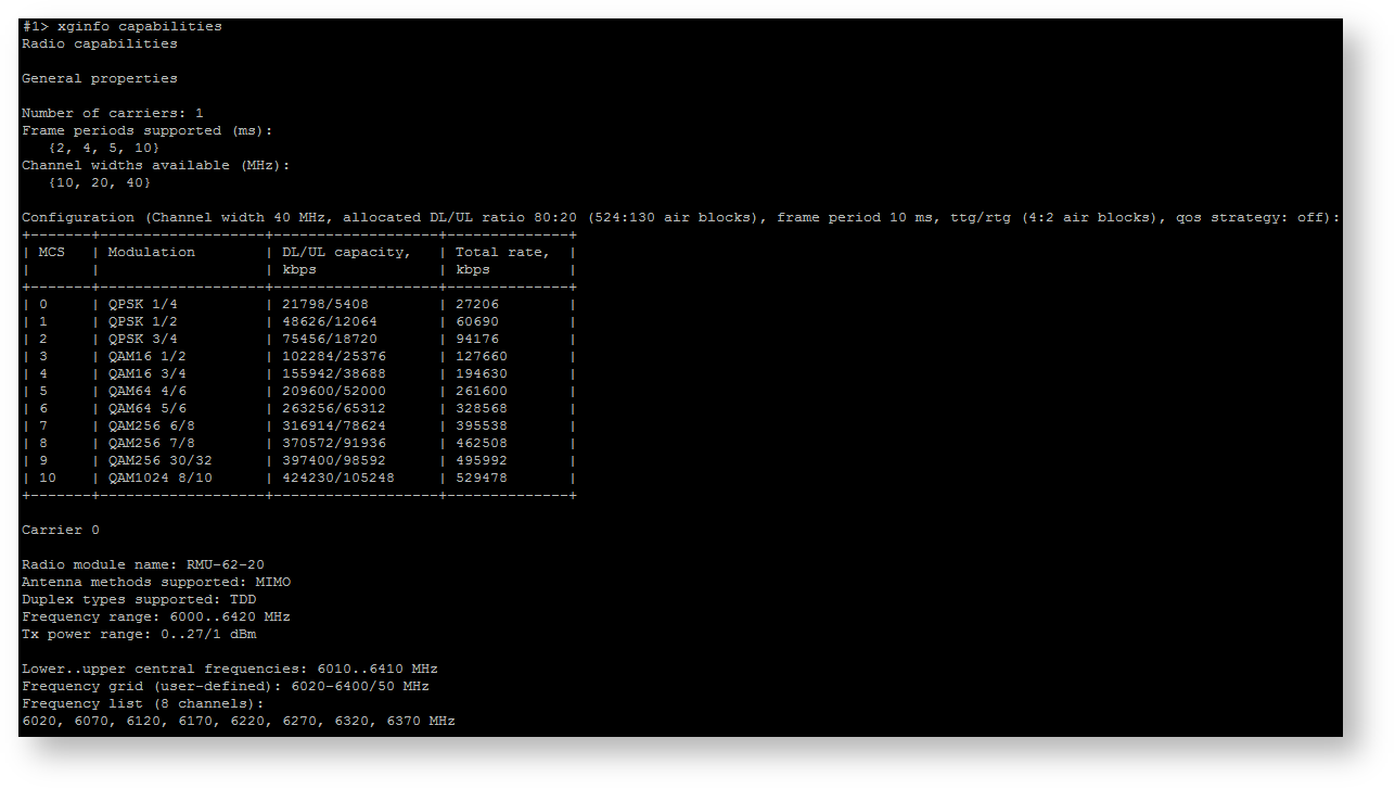 Image Added Image Added
|
|
| Center |
|---|
| Scroll Title |
|---|
| title | Figure - "xginfo version" command output example |
|---|
|  Image Added Image Added
|
|
Syntax:
#1> xgutils [arguments]
| Code Block |
|---|
|
#1> xgutils
usage:
   xgutils ber-amc-show [-carrier <CARRIER_NUM>] [-1]
   xgutils ber-amc-reset [-mask <STREAM_MASK>]

xgutils dfs -list |
"xgutils" command arguments description is given in the table below
| Center |
|---|
| Scroll Title |
|---|
| title | Table - "xgutils" arguments description |
|---|
| | Command | Description |
|---|
| xgutils ber-amc-show [-carrier <CARRIER_NUM>] [-1] | - Displays auto bitrate mechanism counters
| | xgutils ber-amc-reset [-mask <STREAM_MASK>] | - Bitrate adjustment mechanism reset counters based on a bit error counters
| | xgutils dfs -list | - Displays a list of available frequencies and information on them (noise level, radar availability, selected frequency)
|
|
|
| Center |
|---|
| Scroll Title |
|---|
| title | Figure - "xgutils ber-amc-show" command output example |
|---|
| 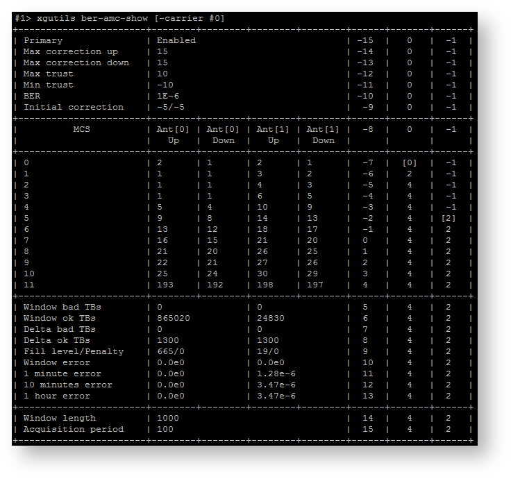 Image Added Image Added
|
|
| Center |
|---|
| Scroll Title |
|---|
| title | Figure - "xgutils dfs -list" command output example |
|---|
|  Image Added Image Added
|
|