The "Radio Settings" contains radio settings, which should be configured to establish wireless connection.
Radio settings are divided into following categories:
Radio frontend
| Center |
|---|
| Scroll Title |
|---|
| title | Radio frontend settings description |
|---|
| | Parameter | Description |
|---|
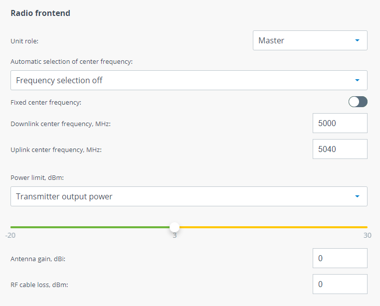
| Unit role | One link unit must be set to Master and the other one to Slave. At the link setup phase the following parameters must be set to the same value on Master unit and Slave unit: - Center frequency - it may be set by two ways:
- Manually via "Downlink center frequency" and "Uplink center frequency" parameters. In this case wireless link will be setup at once.
- Automatically with "Automatic selection of center frequency" function. In this case frequency channel grids must be set on both units. At the initial phase Master unit will select its center frequency automatically from grid, after that Slave unit will scan frequencies from its grid and wireless link will be setup when Slave find the center frequency which Master operates on.
- Channel width - should be set manually on both units.
When a wireless link is established Slave unit will continuously inherit radio frontend parameters from Master unit excluding frequency channel grids. So, if you change some values on Master they will be set on Slave automatically. | | Automatic selection of center frequency | There are several approaches to define center frequencies in Quanta 5: - Frequency selection off - center frequency will be set manually.
- Instant DFS and radar detection - center frequency will be set automatically according to frequency channel grids. In this mode Master unit will switch to the different frequency if high level interference or radar will be detected. Slave unit will switch too at the same time.
- Instant DFS - center frequency will be set automatically according to frequency channel grids. In this mode Master unit will switch to the different frequency only if high level interference will be detected with no matter the type of interference source. Slave unit will be switched too at the same time.
| | Independent UL/DL center frequencies | Units may transmit on diffrerent center frequencies. - Enabled - uplink and downlink frequencies can be set to different values.
- Disabled - uplink and downlink frequencies will be the same.
| | Power limit | Power limit parameter limits the transmitter power, there are two modes: - Transmitter output power - limits the power of transmitter to the set value.
- EIRP - limits the total system power calculated as:
| Center |
|---|
| Code Block |
|---|
Tx Power + Antenna gain + Cable loss |
|
|
|
|
| Center |
|---|
| Scroll Title |
|---|
| title | Figure - Radio frontend settings |
|---|
| 
|
|
Air frame
| Center |
|---|
| Scroll Title |
|---|
| title | Air frame settings description |
|---|
| | Parameter | Description |
|---|
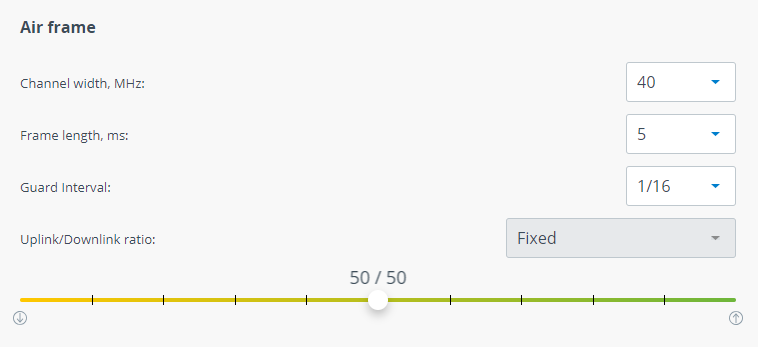
| Channel width | Channel width, shoud be the same on both Master and Slave units. | | Frame period | Frame period affects the following wireless link metrics: - The greater frame period the more payload will be transmitted in one frame. Greater values increase latency.
- The lower frame period the less payload will be transmitted in one frame. Lower values decrease latency.
Please note that frame period value is strongly depends on interference conditions. If larger frames will be dropped then larger payload is lost and system performance is decreased significantly. If smaller frames will be dropped then smaller payload is lost and system performance is decreased not so significantly. | | Guard interval | Guard interval is intended for intersymbol interference elimination. One of the causes of intersymbol interference is multipath propagation in which a wireless signal from a transmitter reaches the receiver via multiple paths. Guard interval affects payload size. So it should be increased only in case of intersymbol interference. | | Uplink/Downlink ratio | Allows to configure quotes for uplink and downlink directions. Available values depend from: - Channel width.
- Frame period.
|
|
|
| Center |
|---|
| Scroll Title |
|---|
| title | Figure - Air frame settings |
|---|
| 
|
|
Automatic modulation and transmit power control
| Center |
|---|
| Scroll Title |
|---|
| title | AMC and ATPC settings description |
|---|
| | Parameter | Description |
|---|
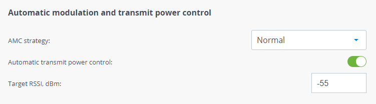
| AMC strategy | There are folowing AMC strategies are available: - Normal - represents a balance between the error rate and throughput values.
- Conservative - assumes using higher CINR thresholds in order to minimize the error rate.
- Agressive - lowers the thresholds in order to use higher modulation levels and thus increase the throughput.
| | Automatic transmit power control | ATPC allows to automatically control transmitter output power. Each unit has its own target RSSI level value calculated automatically. If actual RSSI level is lower then unit increases transmitter output power of the ewmote unit and vice versa. ATPC could not set value that may exceed the "Power limit" value. - The Master unit manages the transmit power of Slave unit.
- The Slave unit manages the transmit power of Master unit.
|
|
|
| Center |
|---|
| Scroll Title |
|---|
| title | Figure - AMC and ATPC settings |
|---|
| 
|
|