...
| Center | |||||
|---|---|---|---|---|---|
|


By clicking the «Start Test»/«Stop Test» buttons at the bottom of the page, you can start/stop the alignment test.
...
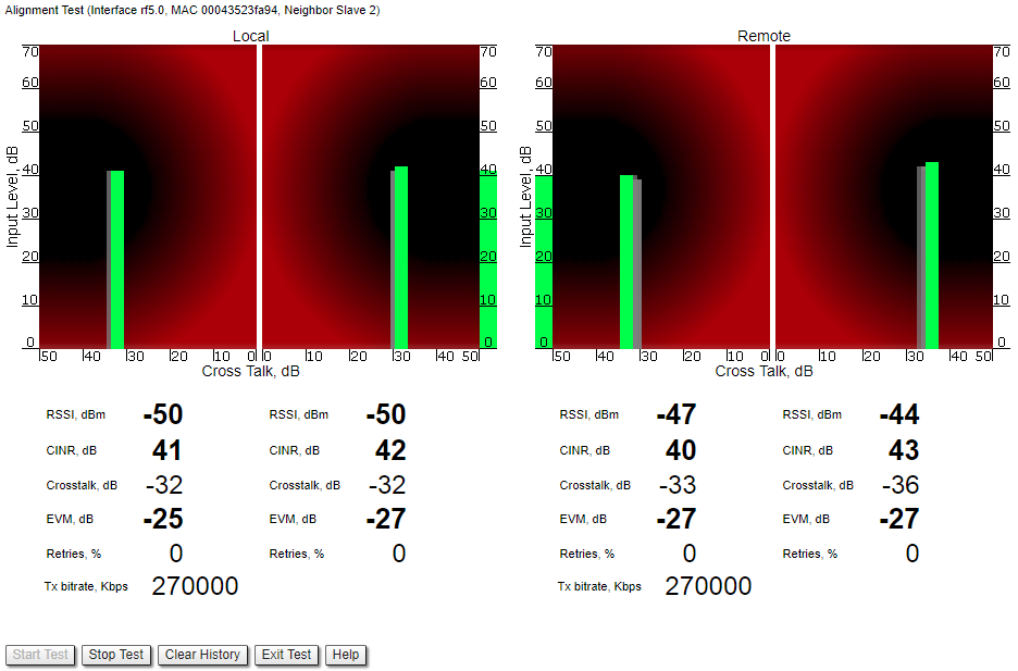
- "RSSI" - indicates the power level of the received radio signal (measured in dBm).
- "Chain 0 Signal LevelCINR" - input signal level to noise + interference (measured in dB) indicator of antenna number 0 (vertical polarization).
- "Chain 1 Signal Level" - input signal level (measured in dB) indicator of antenna number 1 (horizontal polarization)Crosstalk" - indicates how much vertically and horizontally polarized signals influence each other.
- "Error Vector Magnitude (EVM)" - indicator of the measured input signal quality (it should be as high as possible in absolute value; the recommended level is not less than 21 dB; some old firmware had EVM value positive, but most the firmware has negative value, so for the troubleshooting, evaluate the absolute EVM value).
- "Retries" - percentage of transmit packet retries.
- "Tx bitrate" - displays the current bitrate for the remote and local unit (measured in Kbps).
Graphical indicator:
| Center | |||||
|---|---|---|---|---|---|
|

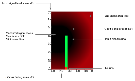
The main indicator is the Input Signal stripe.
...
- It is recommended to start antenna alignment with searching the maximum signal level on a minimal possible bitrate. Afterwards, automatic MINT mechanisms will set the most appropriate bitrate when “Autobitrate” mode is enabled.
- Input signal level (CINR) should be between 12dB and 50dB. It is recommended that ATPC to be disabled
- If signal level is more than 50dB, it is recommended to lower the amplifier power.
- If maximal signal level is less than 12, it is recommended to lower the channel width (for example: from 20MHz to 10MHz).
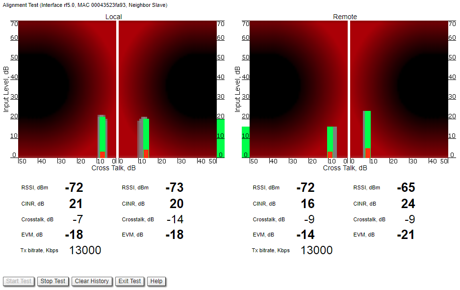
- In some cases, a signal level that is less than 12 may be enough for the radio link operation. In this case, you should be guided by parameters such as the number of retries and Error Vector Magnitude. If the number of retries is low (close to “0”) and EVM is more than 21 (Input Signal stripe is green) then the radio link is most likely, operating properly.
- Retries value should be zero or as low as possible (less than 10%).
- The top of an Input Signal stripe should be located in the black area.
- The signal quality should be good: EVM value should be more than 21.
- Input signals of the two antennas of the device should have similar Cross fading values (Input Signal stripes should be symmetrically to the value of 0dB).
...
| Center | |||||
|---|---|---|---|---|---|
|

- Bad link sample
| Center | |||||
|---|---|---|---|---|---|
|
Statistics Graphs
...