| Hide_commentsinclude | ||||
|---|---|---|---|---|
|
During link planning, such factors as distance, obstacles and , humidity, temperature, atmosphere pressure and the link margin should be taken into account. We . Radio waves in the 70.5-76 GHz frequency range encounter additional atmospheric attenuation beyond that which is expected in free space due to water absorption, including rain fade. The amount of additional atmospheric attenuation will vary, depending on your specific installation environment. So we strongly recommend to use the InfiPLANNER tool for link planning where the rain impact is taken into account.
InfiPLANNER
InfiPLANNER is a link planning tool, which allows to design networks using InfiNet Infinet Wireless devices for optimal deployment and cost effectiveness. It performs different scenarios It accounts for different scenarios based on geography, distance, antenna height, transmit power, device models and other factors. It outputs an installation report that defines the parameters to be used for configuration, alignment and operation. Use the installation report to compare predicted and actual the predicted performance with the actual link performance. InfiPLANNER is available at https://infiplanner.infinetwireless.com.
| Note | ||
|---|---|---|
| ||
You can find more detailed information about InfiPLANNER in the "InfiPLANNER: Link Planning Tool" online course. |
Range and obstacles
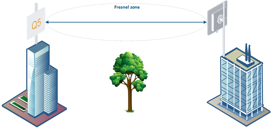
Make sure that line of sight is provided during provided when planning the antennas device placement for a point-to-point link , to in order to achieve maximum range and performance between two antennasdevices. Perform a survey to identify all the obstructions (such as trees or buildings) in the path and to assess the risk of interference.
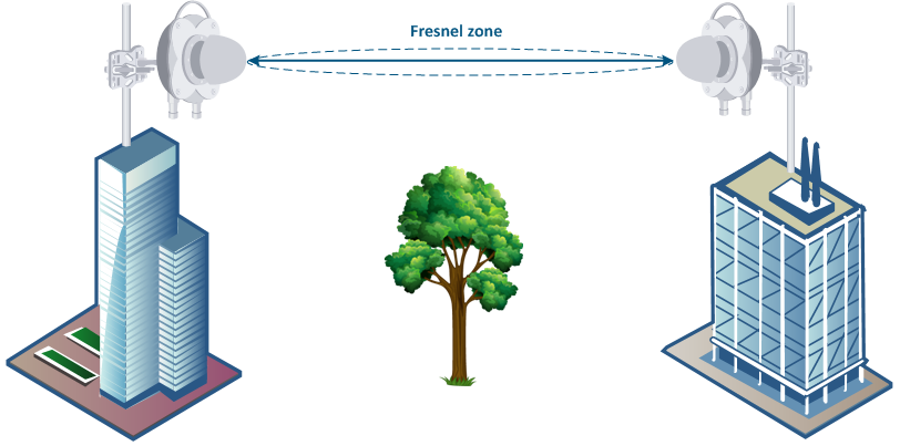
The radio beam is an invisible form of electromagnetic wave propagation and is not as thin as a laser beam, for example. The main energy in a radio beam is concentrated along the straight line between the two antennas, inside an area the shape of an ellipsoid (or a rugby ball). This area is called a 1st Fresnel zone and its exact form and size depends upon the frequency and the signal propagation path length.
If most of the 1st Fresnel zone is obstructed, a major part of the radio wave’s electromagnetic energy is lost, which leads to a severe signal quality degradation and as a result to decreased coverage range or performance
| Warning | ||
|---|---|---|
| ||
Any obstacle in the propagation path is critical for 70 GHz frequency band, make sure the line of sight is 100% clear. |
Below is an incomplete list of possible obstructions on obstructions along the signal propagation path:
- Neighboring buildings.
- Trees.
- Bridges.
- Power lines.
To obtain the best results, it is necessary to perform a precise analysis of the signal propagation path and possible obstructions that may cover the 1st Fresnel zone.
| Center |
|---|
|
| Note | ||
|---|---|---|
| ||
More detailed information about radio signal propagation is available at "Wireless Networking Fundamentals" online course. |
...
Wireless device placement
General recommendations for antenna placementdevice installation:
- Try to keep the LOS clear of obstructionsKeep 100% clear line of sight between devices. In case of installations over vegetation and forest, make sure the direct LOS line of sight stays above the trees; in urban environments - above the tallest buildings along the radio path.
- The influence of trees can be variable, depending on seasons (ice, dew, leaves). Keep in mind that, during spring and summer, leaves can absorb high levels of radio energy. Therefore, when installing during the cold season, over forests and trees without leaves, try to achieve a higher fade margin.
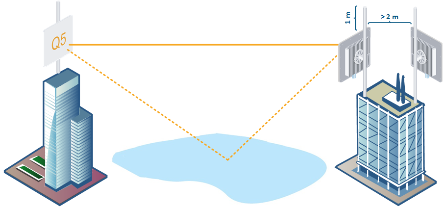
- Install antennas Install wireless devices as far as possible from other antennas radio devices (the recommended distance is at least 2 meters between the edges of the antennas).
- Reflecting surfaces should be considered (buildings with reflective windows, water surfaces or wet grounds). These can be useful in NLOS situations, if there is no direct clear path between the 2 antennas, so the radio signal needs to be reflected off a surface. However, these can also decrease the signal quality when encountered along a clear LOS link, because of fading caused by multipath.
- When installing antennas over water, tune the height bracket within 1-3 meters range variation, because it can yield significant signal level variations due to multipath fading.
- Weather factors such as rain or snow do not usually affect system performance. If seasonal changes influence the signal quality, then the connectors probably are not protected well enough from humidity, or the cables, connectors or antennas are covered by vegetation during summer or ice during winter.
| Center |
|---|
|
...
| title | NOTE |
|---|

Changes or modifications not expressly approved by the party responsible for compliance could void the user’s authority to operate the equipment.
This equipment has been tested and found to comply with the limits for a Class B digital device, pursuant to part 15 of the FCC Rules. These limits are designed to provide reasonable protection against harmful interference in a residential installation. This equipment generates, uses and can radiate radio frequency energy and, if not installed and used in accordance with the instructions, may cause harmful interference to radio communications. However, there is no guarantee that interference will not occur in a particular installation. If this equipment does cause harmful interference to radio or television reception, which can be determined by turning the equipment off and on, the user is encouraged to try to correct the interference by one or more of the following measures:
...
- Install devices from power lines with a voltage higher than 35 kV at a distance at least 100-150 meters.
- Make sure the devices are located outside the area of water streams and splashes formation, which can affect the enclosure for a long time.
- 70 GHz antenna has a very narrow beam, keep devices directed strictly to each other.
| Center |
|---|
|