| Include Page | ||||
|---|---|---|---|---|
|
| Hide_comments |
|---|
| Note | ||
|---|---|---|
| ||
A minimum set of requirements must be met during devices pre-configuration in the lab:
|
Step 1: Scheme connection assembling
...
We will perform the settings mentioned below for each unit of the link and check if the wireless link was established correctly.
...
- Connect Gigabit Ethernet port at the ODU to the power supply port labeled as "OUT".
- Connect Ethernet port at the laptop to the power supply port labeled as "IN".
- Connect the power cord to power supply and plug it to AC mains.
| Center | |||||||||
|---|---|---|---|---|---|---|---|---|---|
|
Step 2: Access to the device
...
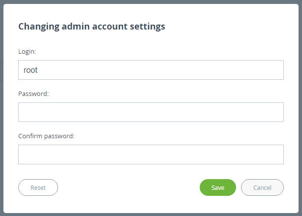
Go to the "Settings" → "Security" section and configure :
- Login (e.g., admin).
- Password (e.g., admin).
...
login and password.
| Center |
|---|
|
| Note | ||
|---|---|---|
| ||
At the next login , type "admin" for the Login and Password (if these are the credentials set before) set up login and password to access the unit in the privileged mode. |
...
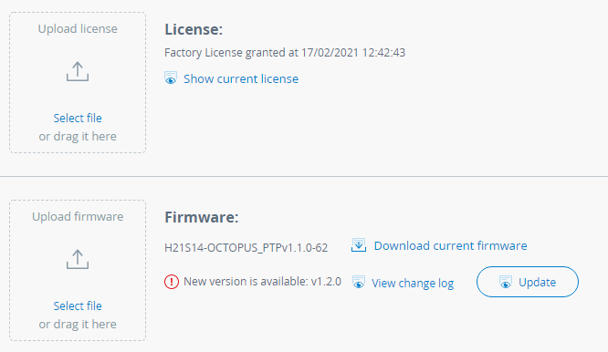
Before, make sure the laptop which is connected to the unit which has an Internet connection, too. Otherwise, the manual firmware upgrade process should be performed:
- Download latest release from the ftp FTP server ftphttps://ftp.infinetInfinet.ru/pub/Firmware.
- In the "Maintenance" section click the "Select file" button and set the path to the downloaded file, or drug it to the specified area.
- File will be uploaded to the device. Changes will take force be applied after reboot.
| Center |
|---|
|
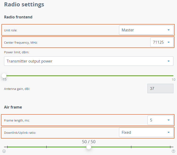
Step 4: Radio parameters configuration
Let's configure the minimum needed radio basic radio parameters needed to establish the link.
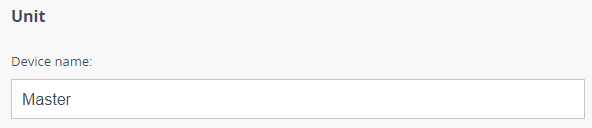
At the unit named Master at step #2 Step 2 above, go to the "Settings" → "General" section and set the "Link ID" parameter, it must be the same on both sides of the link. Then to in the "Radio" and set this unit withsection set the following configuration:
- Unit role: Master.
- Downlink center Сenter frequency: 5200 71125 MHz (use values selected at the Link Planning stage).
- Uplink center frequency: 5200 MHz.
- Power limit: -5 15 dBm (set the minimum value in the range, as currently, we we are in the lab, and we don't need high output power).Channel width: 20 MHz (use value selected at the Link Planning stage).
- Frame length: 5 ms.
- Guard interval: 1/8Fixed Downlink/Uplink ratio.
The rest of other parameters remain with the default values.
| Center |
|---|
|
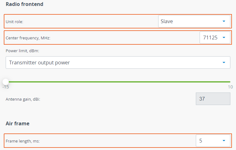
At the unit named Slave at step #2 Step 2 above, go to the "Settings" → "General" section and set the "Link ID" parameter, it must be the same on both sides of the link. Then to in the "Radio" and set this unit withsection set the following configuration:
- Unit role: Slave.
- Downlink center frequency: 5200 71125 MHz (use value selected at the Link Planning stage).
- Power limit: -5 15 dBm (set the minimum value in the range, as currently, we are in the lab, and we don't need high output power).
- Channel width: 20 MHz (use value selected at the Link Planning stage).
- Frame length: 5 ms.Guard interval: 1/8.
The rest of parameters other parameters remain with the default values.
| Center |
|---|
|
Step 5: Check the wireless link status
Let's apply all settings described above for each unit and go to the "Dashboard" section and check if the device status has changed to "Connected".
| Center |
|---|
|
