...
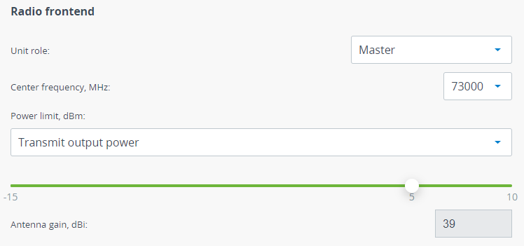
Radio frontend
| Center |
|---|
| Parameter | Description |
|---|
| Unit role | One units must be set to Master and the other one to Slave. Please note that the center frequency must be equal for "master" and "slave" unit to establish the radio link. When a wireless link has been established Slave unit will continuously inherit radio frontend parameters from Master unit excluding frequency channel grid. So, if you change some values on Master they will be set on Slave automatically. | | Center frequency | Frequency should be selected manually in accordance with the actual frequency grid. The Quanta 70 accepts values i range 70500-76000. | | Power limit | This parameter limits the transmitter power, there are two modes: - Transmitter output power - limits the power of transmitter to the set value.
- EIRP - limits the total system power calculated as: Tx Power + Antenna gain
| | Antenna gain | Is set automatically depending on the value of the integrated antenna gain and used for the EIRP limitation. |
|
| Center |
|---|
| Scroll Title |
|---|
| title-alignment | center |
|---|
| title | Figure - Radio frontend settings |
|---|
| 
|
|
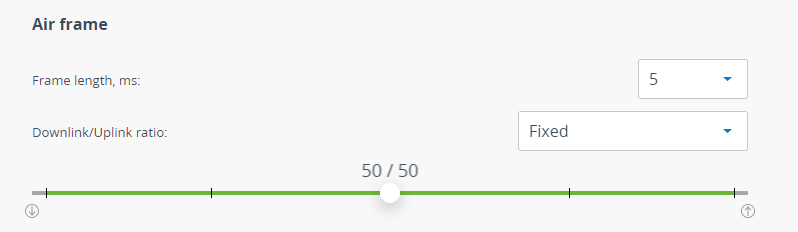
Air frame
| Center |
|---|
| Parameter | Description |
|---|
| Frame length | Frame period affects the following wireless link metrics: - The greater frame period the more payload will be transmitted in one frame. Greater values increase latency.
- The lower frame period the less payload will be transmitted in one frame. Lower values decrease latency.
Please note that frame period value is strongly depends on interference conditions. If larger frames will be dropped the larger payload is lost and system performance is decreased significantly. If smaller frames will be dropped the smaller payload is lost. Following values are available: 0.1; 0.2; 0.5 ;1; 2; 5 ms. | Note |
|---|
| The wireless link distance range depends from the frame length value. The maximum distance for 0.1 and 0.2 ms is listed below: - 0.1 ms – 2.5 km.
- 0.2 ms – 12.5 km.
|
| | Downlink/Uplink ratio | Only for Master device. Allows to configure quotes for uplink and downlink directions. Available values depend from frame length. |
|
| Center |
|---|
| Scroll Title |
|---|
| title-alignment | center |
|---|
| title | Figure - Air frame settings |
|---|
| 
|
|
...
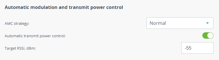
Automatic modulation and transmit power control
| Center |
|---|
| Parameter | Description |
|---|
| AMC strategy | There are following AMC strategies available: - Normal - represents a balance between the error rate and throughput values.
- Conservative - assumes using higher CINR thresholds in order to minimize the error rate.
- Agressive - lowers the thresholds in order to use higher modulation levels and thus increase the throughput.
- Extreme - lowers the CINR threshold below the Aggressive strategy values in order to maximize selected modulation and throughput.
| | Automatic transmit power control | ATPC allows to control transmitter output power automatically based on target RSSI value. If actual RSSI level is lower then unit increases transmitter output power of the remote unit and vice versa. ATPC could not set value that may exceed the "Power limit" value. - The Master unit manages the transmit power of Slave unit.
- The Slave unit manages the transmit power of Master unit.
| | Target RSSI | RSSI value which will be used by ATPC as target. |
|
| Center |
|---|
| Scroll Title |
|---|
| title-alignment | center |
|---|
| title | Figure - AMC and ATPC settings |
|---|
| 
|
|
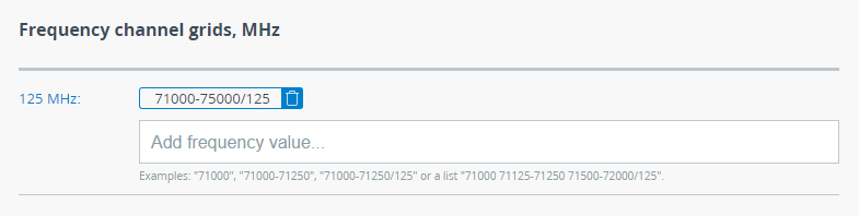
Frequency channel grids
The frequency grid allows to limit the frequency range available to use. Values can be set as a range (71000-72500) or as a list (71500, 73400, 75600) with the step from 0,125 MHz till 10000 MHz.
| Center |
|---|
| Scroll Title |
|---|
| title-alignment | center |
|---|
| title | Figure - Frequency channel grids |
|---|
| 
|
|