...
A backbone link is established between the aggregation node and the network control center. The choice of channel-forming devices is specific devices for the radio link is determined by the transmitted traffic capacity (see Performance of the InfiNet Wireless devices) the . The following throughput values can be achieved:
- InfiLINK 2x2 family devices: upto 280 up to 280 Mbps.
- InfiLINK XG family devices: upto 500 up to 500 Mbps.
- InfiLINK XG 1000 family devices: upto 1000 up to 1000 Mbps.
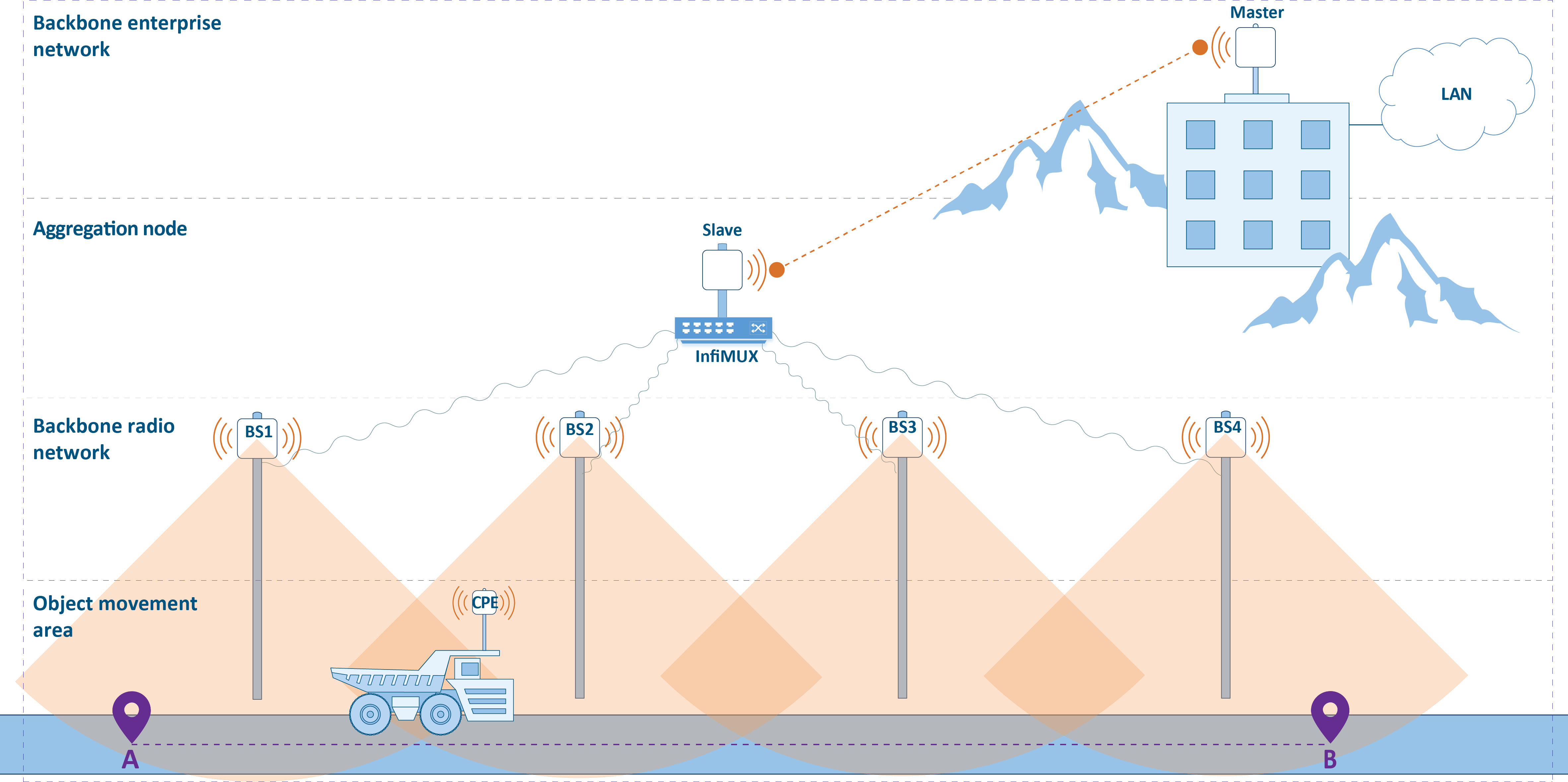
One subscriber A subscriber station (CPE) is installed on each mobile object , the and its configuration contains radio profiles for each BS sector in its area of motion. The operation operational principle is that the CPE can switch the connections while moving between BSthe base stations. Since the BS sectors provide coverage for the entire area in which the CPE can be located, the CPE is always in the coverage area of at least one BS. As soon as the radio parameters of the current connection deteriorate, the CPE breaks CPE interrupts the radio link and connect connects to another sector. So, while the object moving moves from point A to point B (Figure 2) the CPE is connecting one by one to the sectors of BS1, BS2, BS3 and BS4.
Keep in mind that the CPE cannot be simultaneously connected to two BSbase stations, because the device has one radio module, so CPE switching between the BSs is so the roaming between the base station sectors is accompanied by a short-term connectivity break. Several CPEs can be simultaneously connected to one BS sector.
| Center |
|---|
Figure 2 - Areas distributionDistribution of areas |
Fault tolerance and roaming
...