...
In addition to the infrastructure described earlier there is extended an extended list of tasksrequirements, which makes make the solution fault-tolerant and more efficient:
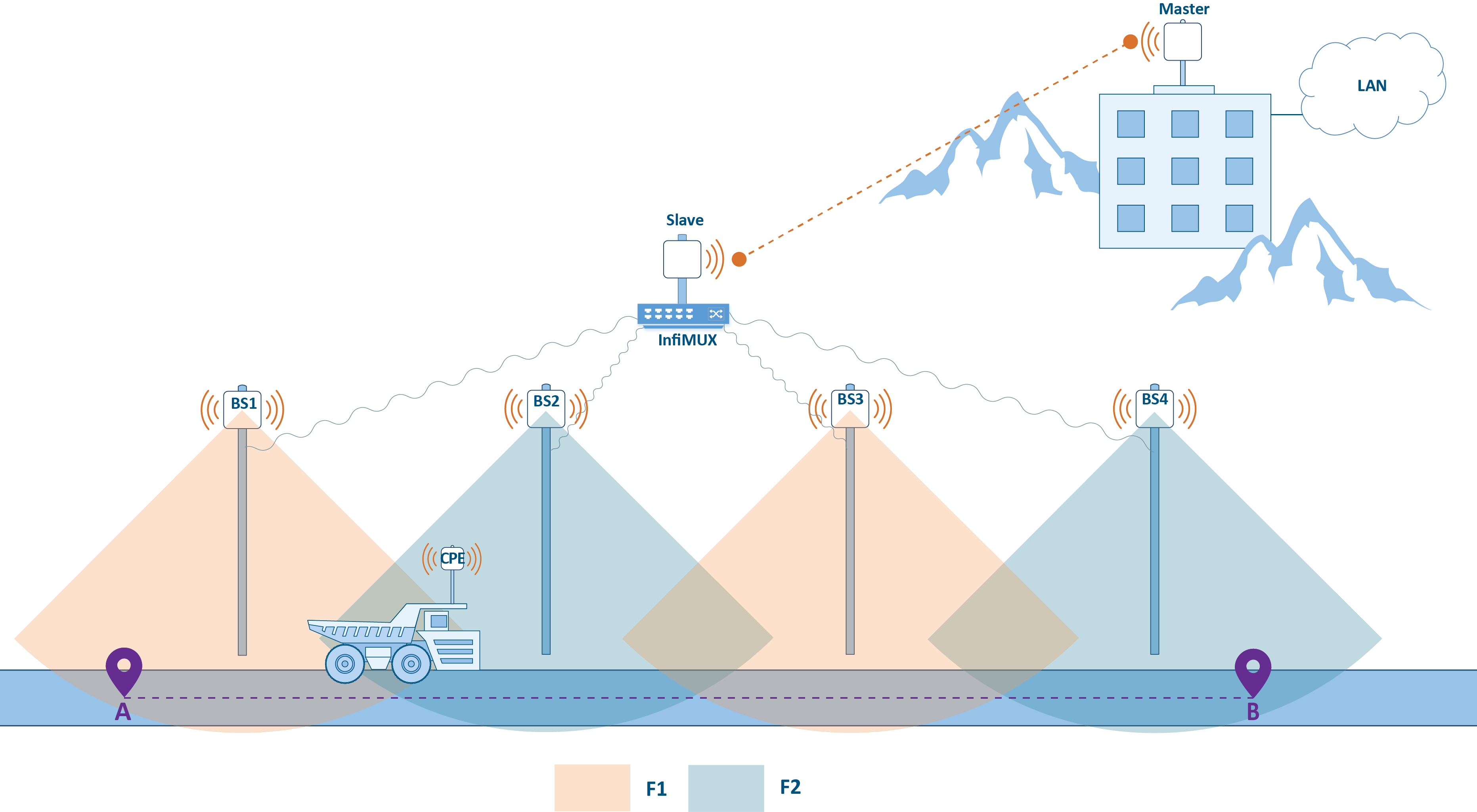
- The link fault tolerance at the access level is ensured by overlapping the sectors' radiation patterns on patterns at the backbone backhaul radio network designing design stage. So, if there is an overlap with neighboring sectors more than 50% overlapping with the neighboring sectors, a failure in one of the sector failure sectors will not affect the coverage area of the radio network. Radio frequency planning requires a complex approach and it is discussed in more detaily detail in the following sections.
- As noted, roaming in the proposed solution is not seamless, because CPE switching between different BS is because the roaming between different base stations is accompanied by a connectivity break. A seamless roaming requires an requires the installation of a second CPE device on each moving object. Such a solution is detaily described below.
- InfiNet devices can be used in various scenarios of point-to-point links link reservation and aggregation. For example, the backbone link can be reserved using the proprietary failover technology which requires an requires the installation of a second backup wireless devices setlink. Failover allows automatic reservation of the backbone link using only one frequency channel. Options The options for organizing link reservations reservation are presented in the Link aggregation, balancing and redundancy document.
An implementation The implementation of a QoS policy does not require the installation of additional devices installation and it is solved by configuring the wireless devices units and the InfiMUX configurationdevice:
- The telemetry gathering service, telephony and the remote control are sensitive to delay and jitter, so they require careful configuration of traffic distribution rules by classes. Low A low jitter for sensitive services can be achieved by using software with versions with TDMA technology support on the InfiMAN 2x2 devices. A comparative analysis of Polling analysis between the Polling and TDMA multiple access technologies is provided in the TDMA and Polling: Application features document.
- The video surveillance service, in addition to the delay requirements, requires the throughput in the uplink from CPE to BS demands an increased throughput in uplink (from the CPE to the BS). The InfiMAN 2x2 devices device family supports the time division multiple access method (TDMA), which allows an administrator flexibly allocate available allows a flexible allocation of the available throughput between the upstream and downstream channels.
- Using a single infrastructure to provide a range of different services requires flexible allocation of available the available throughput between them..
| Anchor | ||||
|---|---|---|---|---|
|
Each the solution implementation is Each implemented solution is unique and requires careful preliminary planning. It is a very important stage, saving resources at the design stage can greatly increase operating the operational costs. Within this document, the radio frequency planning issues and devices placement will of the devices will be reviewed.
RF planning
Frequency planning is a complex, creative process that defines:
- Installation The installation coordinates.
- Suspension The suspension height, azimuth and antenna elevation.
- Devices partnumbersThe part numbers of the devices.
- Frequency The frequency channels and the transmission power.
The result of the frequency planning is a device allocation map with basic radio settings. A convenient tool for radio planning and potential performance assessment depending on the radio parameters is InfiPLANNER.
...
- Regulatory restrictions: RF regulation is determined at the legislative level. Usually, a frequency range it is allocated either a frequency range that is allowed for free use with certain restrictions(radiated power, antenna suspension height , etc.) , and or a frequency range for which the permission must be obtained.
- Radio module capabilities: the wireless device radio module supports of the wireless devices supports a limited set of emitted emission frequencies , this and this should be taken into account at the designing design stage.
- Physical features of the electromagnetic waves propagation: propagation distance, the effect of precipitation and interaction with obstacles are determined by the electromagnetic wave frequency, which must be kept in mind during preliminary calculations. The radio waves propagation effects are detaily described are detailed in the Wireless Networking Fundamentals online course.
- The interference level: the operation of third-party wireless devices has a significant impact on the system's performance, take so it should be taken into account when designing the link. The interference level is affected by the radiation radiated power and the frequency channels used on thirdby the frequency channels used by the third-party devices operating in the areasame area. In addition to interference from third-party devices, the neighboring sectors can have influence on each other. Reducing interference from The reducing of the interference between your own devices can be achieved by using different frequency channels. Recommendations for frequency diversity are given in the TDMA and Polling: Application features document. Particular attention should be paid to the frequency channels channel selection in projects with multisectoral multisector configurations in order to minimize the influence of the BS sectors on each other.
The frequency distribution Some frequency allocation examples are presented below. Figure 3a illustrates a scheme there where each BS sector has it's own frequency channel. This approach requires the allocation of 4 frequency channels.
Let's look at the optimized scheme (Figure 3b). Since the sectors' position is chosen in such a way that the radiation patterns of BS1 and BS3, BS2 and BS4 do not intersect in pairs, they will not interfere with each other. This will optimize the frequency resource usedutilization, reducing the number of frequency channels from 4 to 2.
...
| Center |
|---|
b) Figure 3 - The allocation of frequency channels between BS: a - using four channels, b - using two channels |
Device allocation
The device position in The position of the devices in space determines the actual quality indicators of the wireless link. The position of the device devices is determined by the:
- Installation coordinates.
- Azimuth and antenna elevation.
- Suspension height.
In projects with mobile objects, the antennas antenna's directional properties should be taken into account. If the BSs are static and the radio coverage area is constant, then the CPEs CPE's antenna radiation pattern can greatly affect the link quality. InfiNet's product portfolio includes devices with integrated antennas and the ability to connect external antennas , the device selection is as well. The selection of a specific device is determined by the specific requirements of the project specifics.
The route profile must be evaluated along the entire trajectory of the object trajectory. This will allow to find potential "dead zones" there will be no connection , with no connectivity with the mobile object and . A decision to change the location of the BS if necessaryseveral base stations might be necessary in this case. In addition, perform a survey on enterprise the survey along the enterprise's territory, because the InfiPLANNER link planning tool does not take into account the effects of obstacles such as trees, buildings , etc.
The InfiNet product portfolio includes a wide range of accessories, including mounting kits that allow to install devices in various conditions with the possibility of flexible alignment , and the CAB-RV1 alignment tool which allows to perform preliminary device diagnostics.
The MINT protocol
Ethernet link layer protocol was developed for wired networks and does not take into account the specifics of the wireless environment. Wireless device manufacturers can use standard wireless protocols, such as Wi-Fi, or use their own developments. InfiNet Wireless company is developing a proprietary data transfer protocol called MINT designed for data exchange in a wireless environment.
...