| Include Page | ||||
|---|---|---|---|---|
|
| Hide_comments |
|---|
- Unpack the equipment.
- Check items integrity.
- Initial configuration is required for link establishment.
- Prepare RF cables of the required length. For 5GHz devices, the recommended maximum RF cable length is 1meter.
- Install and seal the connectors on the RF cables.
Important: Horizontal and Vertical polarization should match each other on both sides!
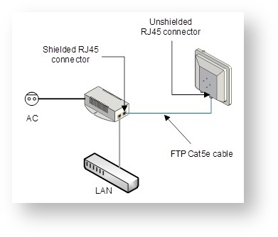
Center Scroll Title title 1 - Antenna ports. Figure - InfiLINK XG UM ODU Model Front Panel - Determine the FTP cable length that is used to connect IDU and ODU. The total cable length between LAN (behind IDU) and ODU should not be longer than 100 meters. Service cable connecting IDU and ODU should be FTP Cat 5E cableFTP Cat5e cable with the outside diameter value not more than 7mm.
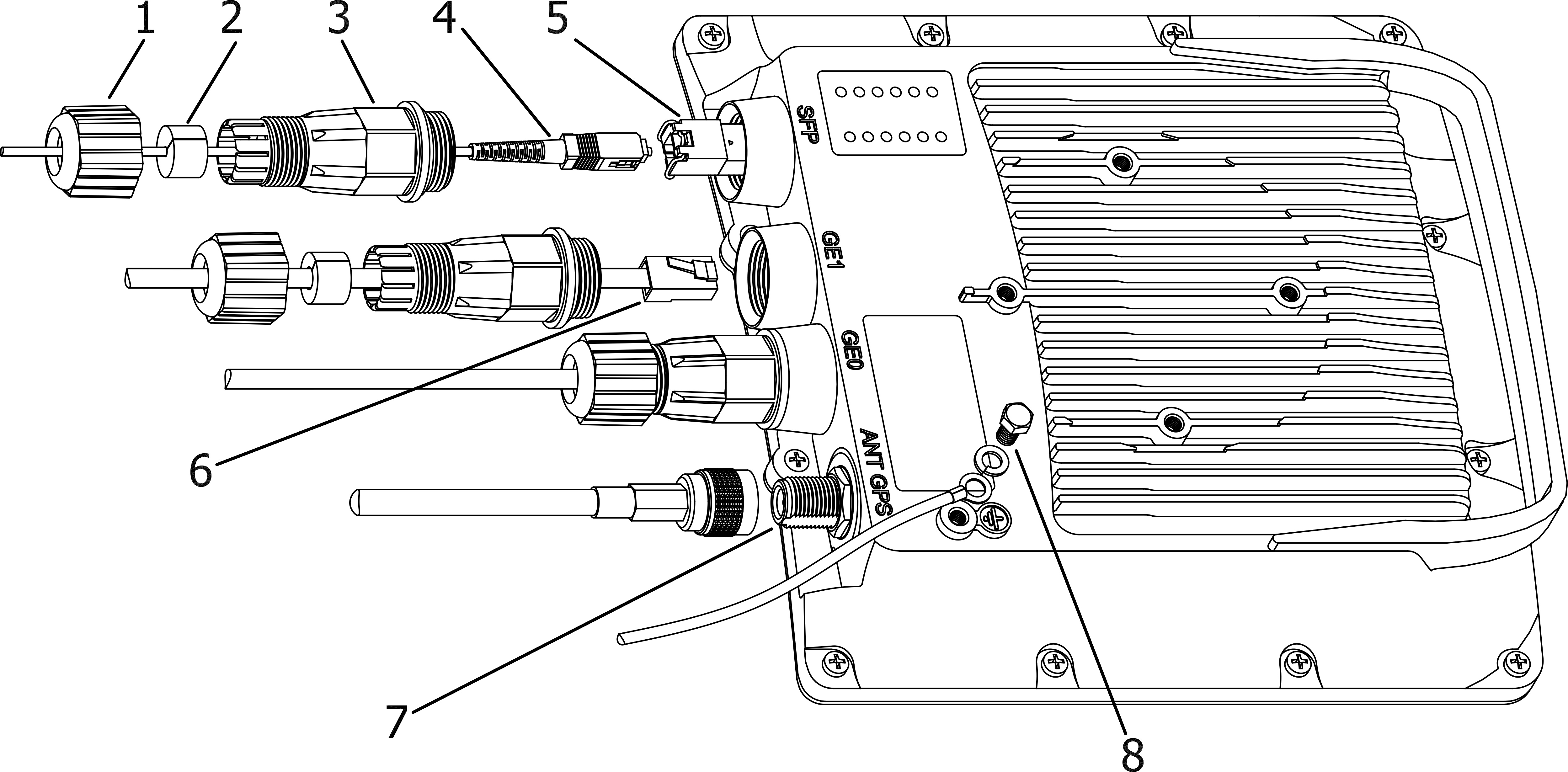
If using SFP module, connect it to ODU, plug in the optical cable (the maximum length and type depend on the SFP module type) and seal the connector
Center Scroll Title title 1 - Cable gland nut, 2 - Split sealing grommet, 3 - Cable gland threaded coupling, 4 - Optical cable (from 2mm to 3mm), 5 - SFP-module (not included in the delivery package), 6 - Standard RJ-45 connector, 7 - GPS antenna port (antenna and cable are not included in the delivery package), 8 - Grounding bolt.
Figure - InfiLINK XG Um ODU Installation Scheme- Install (crimp) regular RJ-45 connector for ODU for ODU on the FTP cable and cable and seal it. Do not use the shielded RJ-45 connector on this end of the cable, as it should be attached only on the IDU the IDU end.
- Lay the FTP cable cable (and the optical cable, if used) “from top to bottom” – from ODU to IDUfrom ODU to IDU.
- Install (crimp and solder) shielded RJ-45 connector for IDU for IDU on the FTP the FTP cable.
Install ODU Install ODU on the mounting bracket, connectors facing down, and tighten it
Note title NOTE .
- Connect the ODUthe ODU-IDU cable to the ODUthe ODU.
- Seal the ODU the ODU Ethernet connectors.
- Once the antenna and antenna pole are installed they must be properly grounded: connected to the building lightning protection circuit. Antenna’s position must be lower than the highest antenna pole point at least by 1 meter. If antenna is NOT DC-shorted (see antenna technical documentation), additional lightning arrestors protection unit must be used which are placed between ODU between ODU and antenna and are grounded to the antenna pole grounding circuit.
- Connect the RF the RF cables to the antenna ports, minding the polarization marks. Twist the connectors tightly.
- Connect the RF the RF cables to the ODU the ODU ports, after previously having touched the RF the RF cables’ connector case with ODU with ODU connector case.
- Seal RF Seal RF connectors from both sides (ODU and antenna).
Connect the FTP
cable tocable to IDU, after previously having
touched IDUtouched IDU connector case with FTP
cable connector caseProvide grounding for IDUcable connector case.
Warning title CAUTION The power supply must not operate near a direct heat source, near water or in an environment with high humidity. The cables must be connected in such a way to prevent water flow to the power supply connectors.
- Provide grounding for IDU.
- Connect Ethernet cable to IDUto IDU.
- Connect the IDU the IDU to power.
- Connect to the Device using Telnet protocol.
| Note | ||
|---|---|---|
| ||
It is very important to mount the ODU connectors facing down. |
| Center | |||||||||||||||||||||||||||
|---|---|---|---|---|---|---|---|---|---|---|---|---|---|---|---|---|---|---|---|---|---|---|---|---|---|---|---|
|
| Warning | ||
|---|---|---|
| ||
Before supplying power to the Um models an external antenna or RF terminators with 50 Ohms resistance must be connected to both N-type connectors. During laboratory testing, it is allowed to directly connect two devices with RF cables without antennas with the mandatory use of attenuators with attenuation of at least 40 dB for each polarization. Switching off/on the attenuators and RF cables should only be performed when the devices are in the off state. In case the antenna, attenuator or terminator is connected to only one N-type connector do not switch on the device. PLEASE NOTE THAT VIOLATION OF THE ABOVE REQUIREMENTS VOIDS THE WARRANTY. |
| Note | ||
|---|---|---|
| ||
If there is no data transfer via one of the device ports (GE0 or GE1), the second port can be used as a backup for data transfer. THE DEVICE IS OUT OF WARRANTY IN THIS CASE. |
| Warning | ||
|---|---|---|
| ||
Please note that the pressure equalization system in Infinet devices is performed via gas exchange through a cable gland and Ethernet cable jacket with a dry room where the power supply is installed. In order to avoid ODU failure due to moisture entering the device, for example, during the pressure drop during the rain, the cable gland assembly requirements should be met and there are should be no cracks in the Ethernet cable jacket. In addition, you should avoid the Ethernet cable bending near the ODU and pinching with clamps, that can bring to the pressure equalization system fault between the internal volume of the sealed ODU and the external environment during a sudden air temperature change. This may lead to the leakage and device failures. |