...
Settings via web interface
| Anchor | ||||
|---|---|---|---|---|
|
| Step 1 | ||||||||||
|---|---|---|---|---|---|---|---|---|---|---|
Access the unit to the default IP address 10.10.10.1 with mask 255.255.255.0 via web browser. Make sure that the Ethernet port of the Laptop has an IP address assigned from the same subnetwork as the one for the unit (for example, set 10.10.10.50 with mask 255.255.255.0). | ||||||||||
| Step 2 | ||||||||||
Use any letters or numbers for initial authentication, for example:
| ||||||||||
| Step 3 | ||||||||||
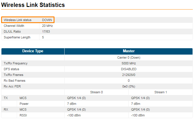
Log in to the Web GUI. Initially the status of the radio link is DOWN like below.
| ||||||||||
| Step 4 | ||||||||||
Upgrade the units to the latest stable firmware version.
| ||||||||||
| Step 5 | ||||||||||
Perform radio settings. Go to the "Radio" section and set the following parameters:
| ||||||||||
| Step 6 | ||||||||||
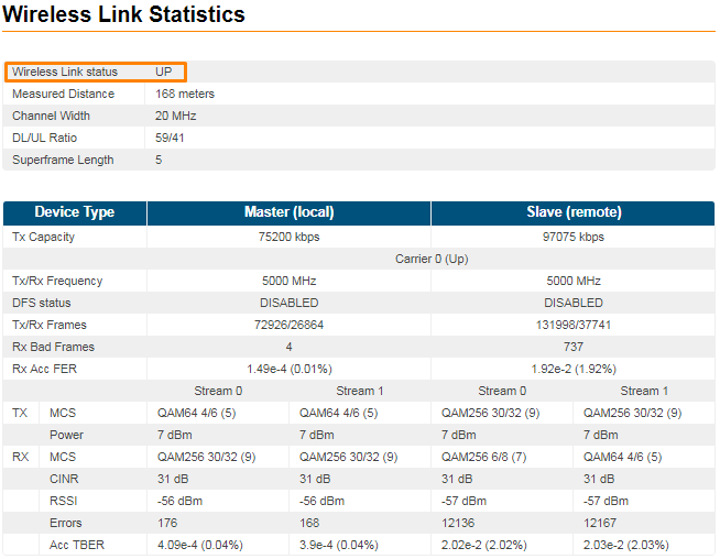
Save the configuration, reboot both units and check if they link is up. The link status should be UP and the radio statistics should indicate the capabilities and quality of the link.
|
Settings via CLI
| Anchor | ||||
|---|---|---|---|---|
|
...