...
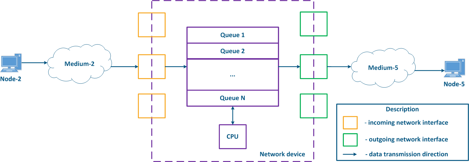
- Node-2 forms a data packet and transmits it to EnvironmentMedium-2. The data packet is encapsulated in L2-protocol frame used in EnvironmentMedium-2.
- The data frame is distributed in EnvironmentMedium-2. The frame is converted into a modulated signal in accordance with an environment physical properties. Signals used in wired and wireless environments are different, which affects their propagation properties and usage scenarios.
- The signal arrives at the input device interface; after demodulation, the received data frame is checked for integrity: damaged frames are discarded.
- The next stage - routing determines frames further path. If the frame is addressed to a Network device, it is passed for processing to internal services. If the frame is addressed to another node, two scenarios are possible: the frame must be passed further through the output interface, or discarded (if EnvironmentMedium-2 is a common environment, where all signals will be received by all devices connected to the environmentmedium. In accordance with the L2 protocols operational principles, if the receiver address in the frame header does not belong to the device, then the device should discard it).
- In case the frame should be processed and transferred to another node, it enters the packets queue. A packets queue is a set of buffers that contain data received by incoming interfaces. The number and size of memory buffers for the packets queue storage are not standardized and depend on the equipment manufacturer. For example, the InfiLINK 2x2 devices family has 32 queues, 17 of which are available for configuration by user.
- The data frame passes through the packets queue to which it was placed, and enters the outgoing interface.
- Since packets queues are a link between incoming and outgoing interfaces, a device should have a controller that fills the queues with incoming data and picks data from the queues for transmission to outgoing interfaces. Usually, these functions are performed by the central processing unit (CPU). As will be shown below, the filling and picking data from queues can be performed unevenly and depend on the data streams classification.
- The outgoing interface generates a modulated signal and transmits it to EnvironmentMedium-5 with connected Node-5, which is the receiver of the original data frame.
- Node-5 receives a signal, demodulates it, and processes the received data frame.
Note, in the modern network devices, network interfaces mostly are combined and can operate operate both as both incoming and outgoing.
| Center |
|---|
Figure 1 - A network device traffic passing scheme |
...
- The communication channel and network devices throughput is finitenot endless.
- The data delivery time from source to destination is non-zero.
- A communication channel is an environment with a medium with a set of physical parameters that define the signal propagation effects.
- The software and hardware network device architecture can affect the data distribution.
...
Let's look at the example (Figure 8), Node-2 generates several services traffic with a total speed of 1 Gbit/s, EnvironmentMedium-2 allows to transfer this data stream to an intermediate network device, however, the maximum link throughput between network device and Node-5 is 500 Mbps. Obviously, the data stream cannot be processed completely and part of this stream must be dropped. The QoS task is to make this drops manageable to provide the end services the required metric values. Of course, it is impossible to provide the required performance for all services, as links throughputs do not match, therefore, the QoS policy implementation involves that critical services traffic should be processed first.
...
- Step 1:
- Node-1 and Node-2 generate packets of two services: telephony and mail. The telephony traffic is sensitive to delay and jitter unlike mail service data (see Services requirements for quality indicators), therefore, it must be processed first by the intermediate devices.
- Network device-1 receives Node-1 and Node-2 packets.
- Step 2:
- Traffic prioritization is configured on Network device-1, thus the device classifies incoming traffic and places data packets in different queues. Whole telephony traffic will fall in queue 0, and mail traffic in queue 16. Thus, the queue 0 priority is higher than queue 16.
- Packets leave queues and proceed to outgoing interfaces in accordance with the queues priorities i.e. queue 0 will be emptied first, then queue 16.
- Step 3:
- Network device-1 sends data to EnvironmentMedium-7, connected with Network device-2. The data packets sequence corresponds to quality metrics - telephony data is transmitted to environment medium first, and the mail service next.
- Node-3 is connected to Network device-2 and generates a mail service data stream.
- Step 4:
- The Network Device-2 has no prioritization settings, thus all incoming traffic falls in the queue 16. Data will leave queues in the same order they entered, i.e. telephony and mail service traffics will be handled equally, despite the requirements for the quality indicators.
- Сетевое устройство-2 вносит задержку во время распространения трафика телефонииNetwork device-2 increase a delay during the telephony traffic transmission.
- Step 5:
- Data are transmitted to the end nodes. The telephony packets transmission time was increased due to the Node-3 mail service traffic processing.
...