...
| Center |
|---|
Figure 5 - Example of data transfer delay |
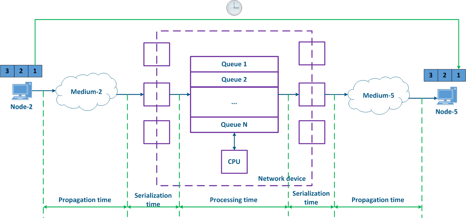
Jitter
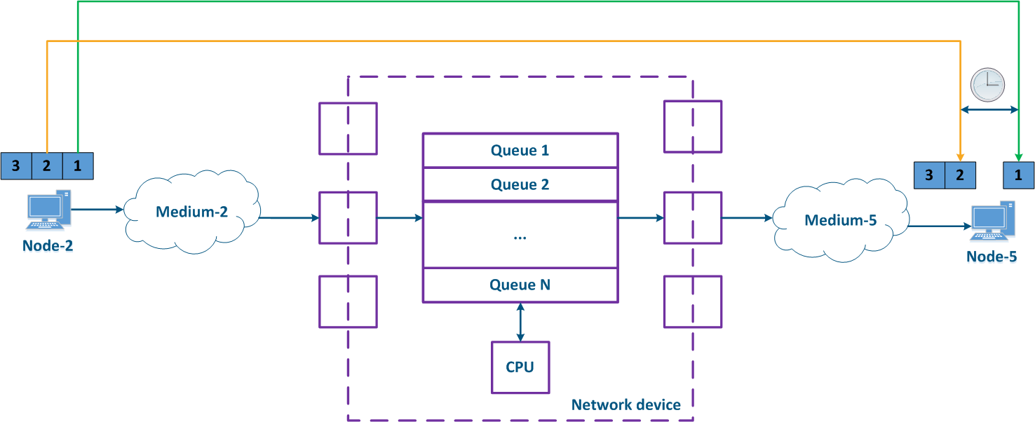
The CPU loading load and the packets packet queues status on intermediate network devices are frequently changing at the intermediate network devices, so the delay during the data packets packet transmission can changewill vary. In the example below (Figure 6), the transmission time of for the packages with the identifiers 1 and 2 is different. The difference between the maximum and the average delay values is called jitter.
| Center |
|---|
Figure 6 - Example of floating varying delay in data transfer |
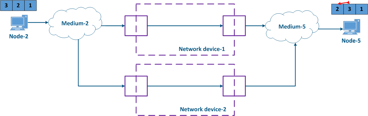
In When using a redundant network infrastructure the data between the source and the receiver can be transmitted in various ways, it will also lead to the jitter appearancethrough different paths,so jitter will occur. Sometimes the difference between the delays in the link on each path may become so large that the order of the transmitted data packets order will change on the receiving side (Figure 7). In the example below, the packets with identifiers were received in a different order.
The effect depends on the characteristics of the service characteristics and on the ability of the higher layer network protocols to restore the original sequence by higher levels network protocols. For example, if the traffic of different services is transmitted through different paths, then it will should not affect the disorder ordering of the received data.
| Center |
|---|
Figure 7 - Example of unordered data delivery delivery |
| Anchor | ||||
|---|---|---|---|---|
|
...
Service requirements with respect to the quality indicators
Each of the data transfer services has a set of requirements set for the quality indicators. The RFC 4594 document includes the following service types:
...
| Expand | |||||||||||||||||||||||||||||||||||||||||||||||||||
|---|---|---|---|---|---|---|---|---|---|---|---|---|---|---|---|---|---|---|---|---|---|---|---|---|---|---|---|---|---|---|---|---|---|---|---|---|---|---|---|---|---|---|---|---|---|---|---|---|---|---|---|
| |||||||||||||||||||||||||||||||||||||||||||||||||||
| |||||||||||||||||||||||||||||||||||||||||||||||||||
QoS
...
methods
The various services traffic transmission of the various services is performed on a single network infrastructure, which has limited resources, therefore, mechanisms should be provided for distributing the resources distribution between the services.
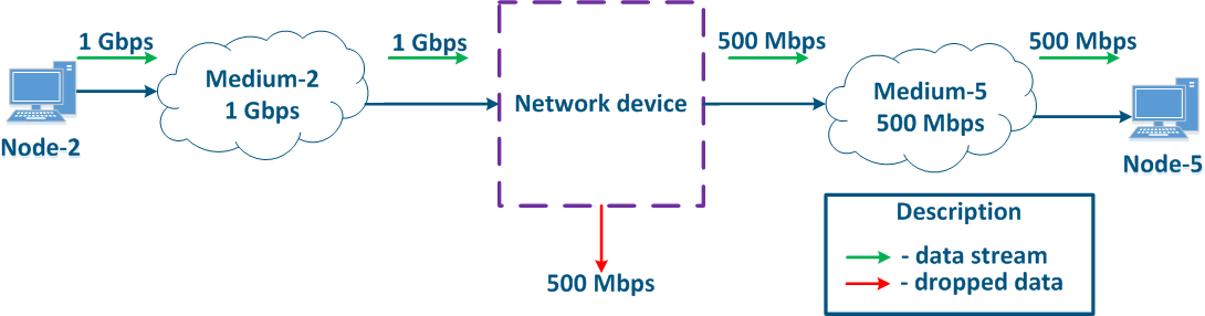
Let's look at the example below (Figure 8), . Node-2 generates several traffic serving different services traffic with a total speed of 1 Gbit/s, . Medium-2 allows to transfer this data stream to an intermediate network device, however, the maximum link throughput between network the Network device and Node-5 is 500 Mbps. Obviously, the data stream cannot be processed completely and part of this stream must be dropped. The QoS task is to make this these drops manageable in order to provide the end services the required metric values for the end services. Of course, it is impossible to provide the required performance for all the services, as links throughputs do the throughput does not match, therefore, the QoS policy implementation involves that the traffic of the the critical services traffic should be processed first.
| Center |
|---|
Figure 8 - Example of inconsistency in between the incoming traffic amount and links throughputsthe link throughput |
The example above allows shows to highlight two main methods used in during the QoS policy implementation:
- Prioritization: data distribution among queues and packets selection from the queues by priority. In this case, the packets that are most sensitive to delay and jitter are processed first, then the traffic , for which the delay value is not critical is processed.
- Throughput limitation: throughput limitation for traffic flows. All the traffic that exceeds the set throughput threshold will be discarded.
Let's look at the example above, and add the a second intermediate device to the data distribution scheme (Figure 9a). The packets packet distribution scheme has follows the following next steps:
- Step 1:
- Node-1 and Node-2 generate packets of for two services: telephony and mail. The telephony traffic is sensitive to delay and jitter unlike the mail service data (see Services requirements for quality indicators), therefore, it must be processed first by the intermediate devices.
- Network device-1 receives the packets of Node-1 and of Node-2 packets.
- Step 2:
- Traffic prioritization is configured on Network device-1, thus the device classifies the incoming traffic and places the data packets in different queues. Whole telephony All the voice traffic will fall be put in queue 0, and the mail traffic will be put in queue 16. Thus, the priority of queue 0 priority is higher than the one of queue 16.
- Packets The packets leave the queues and proceed to towards the outgoing interfaces in accordance with the queues queue priorities i.e. queue 0 will be emptied first, then queue 16 will be emptied.
- Step 3:
- Network device-1 sends data to Medium-7, which is connected with the Network device-2. The data packets sequence corresponds of data packets corresponds to the quality metrics - telephony data is transmitted to first through the medium first, and the mail service is sent next.
- Node-3 is connected to Network device-2 and generates a mail service data stream.
- Step 4:
- The Network Device-2 has no prioritization settings, thus all the incoming traffic falls is put in the queue 16. Data The data will leave the queues in the same order they that it entered, i.e. the telephony and the mail service traffics services will be handled equally, despite the requirements for of the quality indicators.
- Network device-2 increase a increases the delay during for the telephony traffic transmission.
- Step 5:
- Data are The data is transmitted to the end nodes. The telephony packets transmission time of the voice packets was increased due to the additional processing of the mail service traffic of Node-3 mail service traffic processing.
Each intermediate network device without traffic prioritization settings will increase the data transmission delay, and the delay amount is unpredictable. Thus, a large number of intermediate devices will make real-time services operation impossible because of the quality indicators unattainability, i.e. traffic prioritization must be done along the entire network traffic transmission path (Figure 9b).
...