...
The processing priority of a packet can be set using the service fields of various network protocols. This article describes the use of the Ethernet and of the IPv4 protocol headers.
...
Ethernet (802.1p) frame prioritization
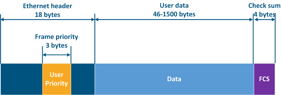
The Ethernet frame header includes the "User Priority" service field, which is used to prioritize the data frames. The field has a 3 bits size, which allows to select 8 traffic classes: 0 class - the lowest priority class, 7 class - the highest priority class. Keep in mind that the "User Priority" field is present only in 802.1q frames, i.e. tagged with the VLAN tagframes using VLAN tagging.
| Center |
|---|
Figure 11 - Frame prioritization service field in the Ethernet header |
...
IP packet prioritization
The IP protocol has three historical stages in the development of the service field responsible for packets packet prioritization:
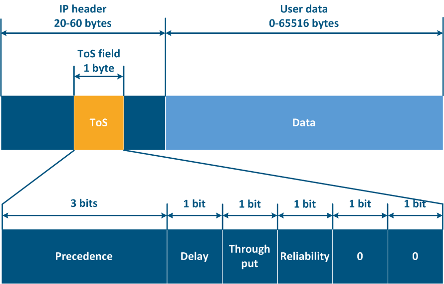
- When the protocol was first approved, there was an 8-bit ToS (Type of Service) field in the IP packet header (see RFC 791). ToS included the following fields (Figure 12a):
- Precedence: priority value.
- Delay: delay minimization bit.
- ThorughputThroughput: throughput minimization bit.
- Reliability: reliability maximization bit.
- 2 bits with values are equal to 0.
- In the second stage, 8 bits were still used for packets prioritization, however, ToS had included the following fields (see RFC 1349):
- Delay.
- Throughput.
- Reliability.
- Cost: bit to minimize the cost metric (1 bit is used, which whose value was previously zero).
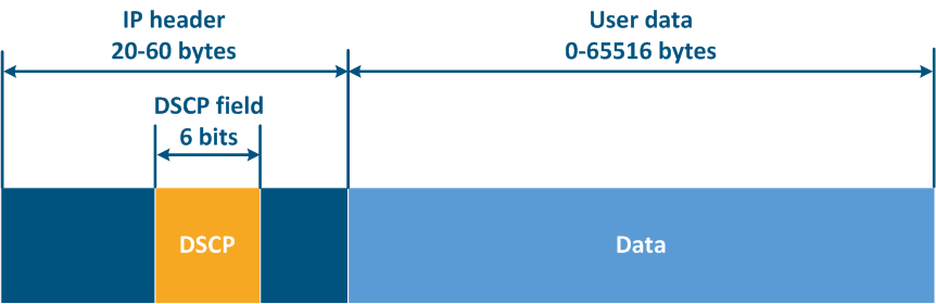
- Last, the IP header structure has been changed (see RFC 2474).The 8 bits previously used for prioritization were distributed in a the following way (Figure 12b):
- DSCP (Differentiated Services Code Point): packet priority.
- 2 bits are reserved.
...
| Center |
|---|
Figure 12a - ToS service field in the IP packet header
Figure 12b - DSCP service field in the IP packet header |
Priority configuration
Many end nodes on in the network do not support manipulation with the handling of the service headers: can not set or remove the priority, so this functionality should be implemented on the corresponding intermediate network devices.
Let's look at the example of a data transmission from Node-1 to Node-2 through a DS-domain and through a third-party telecom operator's network (Figures 13a-c). The DS domain includes three devices, two of them for are located at the domain are borderline and one is an intermediate device. Lets look at the steps of data processing data in a network using an Ethernet frame transmission (the basic principles discussed in the example below are applicable for an IP packet or other protocol that supports data prioritization):
- Step 1: Node-1 generates an Ethernet frame for Node-2. There is no field present for frame priority tag tagging in the header header (Figure 13a).
- Step 2: Border Network Device-1 changes the Ethernet header, setting the priority to 1. Border devices should have rules configured rules to select in order to filter the traffic of Node-1 traffic from the general stream so necessary priority is set only to these framesand assigna priority for it (usually the traffic of several devices is aggregated using a switch before reaching Border network device-1, but this is a simplified example). In networks with a large traffic flows number, the list of rules on border devices can be volumetric. Border network device-1 processes the frame in accordance with the set priority, placing it in the corresponding queue. The frame is transmitted to the outgoing interface and sent to the Intermediate network device-2 direction (Figure 13a).
- Step 3: Intermediate network device-2 receives an Ethernet frame with priority 1, and places it in the corresponding queue. The device does not manipulate with setting/removing priority in the frame header. The frame is transmitted towards the Border network device-3 (Figure 13a).
- Step 4: The border network device-3 processes the incoming frame similarly as Intermediate device-2 (see Step 3) and transmits it to the provider network (Figure 13a).
- Step 4b: in case of agreement that traffic will be transmitted through the provider network with a priority other than 1, then the Border Device-3 must perform a priority change. In this example, the device changes the priority value from 1 to 6 (Figure 13b).
- Step 5: during the frame transmission through the provider network, the devices are guided by the priority value in the Ethernet header (Figure 13a).
- Step 5b: similarly to Step (Figure 13b).
- Step 5c: in there is no agreement about frames prioritization in accordance with the priority value specified in the Ethernet header, a third-party service provider can apply its own QoS policy to traffic and set a priority that may not satisfy the QoS policy of the DS domain (Figure 13c).
- Step 6: the border device in the provider network removes the priority field from the Ethernet header and passes it in the Node-2 direction (Figure 13a-c).
...