...
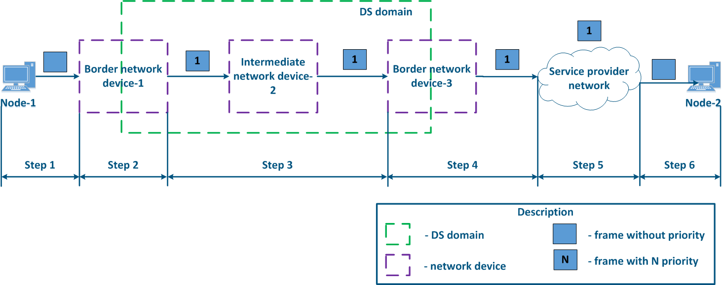
- Step 1: Node-1 generates an Ethernet frame for Node-2. There is no field present for frame priority tagging in the header (Figure 13a).
- Step 2: Border Network Device-1 changes the Ethernet header, setting the priority to 1. Border devices should have rules configured in order to filter the traffic of Node-1 from the general stream and assigna priority for it (usually the traffic of several devices is aggregated using a switch before reaching Border network device-1, but this is a simplified example). In networks with a large traffic flows flow number, the list of rules on border devices can be volumetric. Border network device-1 processes the frame in accordance with according to the set priority, placing it in the corresponding queue. The frame is transmitted to towards the outgoing interface and sent to the Intermediate network device-2 direction (Figure 13a).
- Step 3: Intermediate network device-2 receives an the Ethernet frame with having priority 1, and places it in the corresponding priority queue. The device does not manipulate with setting/removing priority in handle the priority in terms of changing or removing it inside the frame header. The frame is next transmitted towards the Border network device-3 (Figure 13a).
- Step 4: The border Border network device-3 processes the incoming frame similarly as to the Intermediate device-2 (see Step 3) and transmits forwards it to towards the service network provider network (Figure 13a).
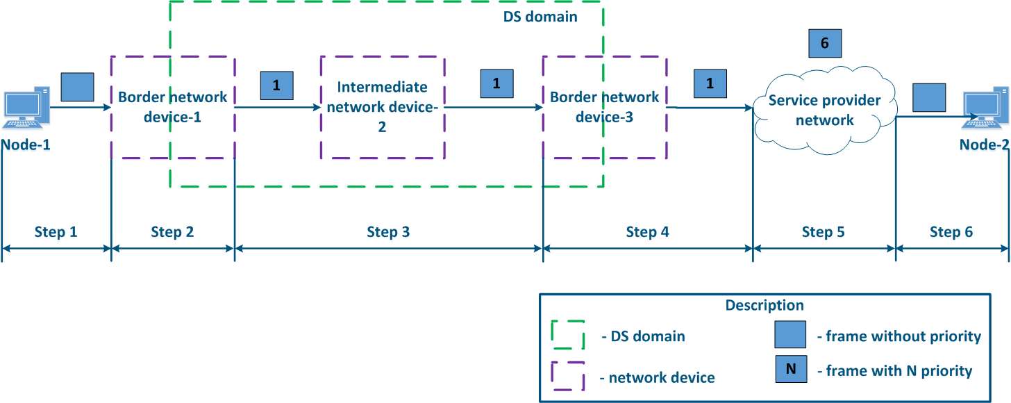
- Step 4b4a: in case of agreement agreeing that the traffic will be transmitted through the provider's network with a priority other than 1, then the Border Device-3 must perform a priority change. In this example, the device changes the priority value from 1 to 6 (Figure 13b).
- Step 5: during the transmission of the frame transmission through the provider's network, the devices are guided by will take into account the priority value in the Ethernet header (Figure 13a).
- Step 5b5a: similarly to Step 4a (Figure 13b).
- Step 5c5b: in if there is no agreement about frames prioritization in accordance with the frame prioritization according to the priority value specified in the Ethernet header, a third-party service provider can apply its own QoS policy to traffic and set a priority that may not satisfy the QoS policy of the DS domain (Figure 13c).
- Step 6: the border device in the provider's network removes the priority field from the Ethernet header and passes forwards it in the to Node-2 direction (Figure 13a-c).
| Center |
|---|
Figure 13a - Example of the Ethernet frame priority changing during the transmission through two network segments (the priority in segments settingis coordinated and the priority value matches for the 2 segments)
Figure 13b - Example of the Ethernet frame priority changing during the transmission through two network segments (the priority in segments settingis coordinated, but the priority should be changed)
Figure 13c - Example of the Ethernet frame priority changing during the transmission through two network segments (the priority setting in the 2 segments is not coordinated) |

...