Table of
...
contents
| Table of Contents |
|---|
| maxLevel | 3 |
|---|
| exclude | Содержание |
|---|
|
...
Route redistribution from ODR to OSPF
Let's look at the an example of routing information redistribution from the ODR protocol to the OSPF protocol, using the network scheme described in the main document (Figure 1).
| Center |
|---|
 Image Removed Image Removed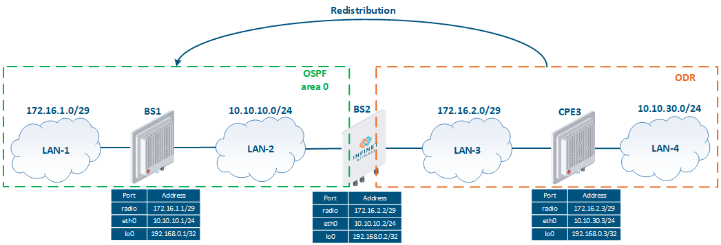 Image Added Image Added
Figure 1 - Route redistribution scheme from ODR to OSPF |
Pre-configuration
| Description | Perform a devices preliminary configuration of the devices, consisting of the following steps: - Configure the device IDIDs.
- Remove the svi1 interface.
- Assign IP addresses to the network interfaces, according to the scheme.
- Disable switching.
- Set Establish the wireless links.
|
|---|
| BS1 | | Code Block |
|---|
| Set the device ID
system prompt BS_1
Remove the svi1 interface
ifc svi1 destroy
Assign IP addresses
ifc eth0 10.10.10.1/24
ifc rf5.0 172.16.1.1/29
ifc lo0 192.168.0.1/32
Disable switching
switch stop
SetEstablish the radio link
rf rf5.0 band 20
rf rf5.0 freq 5100
mint rf5.0 -name "BS_1"
mint rf5.0 -type master |
|
|---|
| BS2 | | Code Block |
|---|
| Set the device ID
system prompt BS_2
Remove the svi1 interface
ifc svi1 destroy
Assign IP addresses
ifc eth0 10.10.10.2/24
ifc rf5.0 172.16.2.2/29
ifc lo0 192.168.0.2/32
Disable switching
switch stop
SetEstablish the radio link
rf rf5.0 band 20
rf rf5.0 freq 5000
mint rf5.0 -name "BS_2"
mint rf5.0 -type master |
|
|---|
| CPE3 | | Code Block |
|---|
| Set the device ID
system prompt CPE_3
Remove the svi1 interface
ifc svi1 destroy
Assign IP addresses
ifc eth0 10.10.30.3/24
ifc rf5.0 172.16.2.3/29
ifc lo0 192.168.0.3/32
Disable switching
switch stop
SetEstablish the radio link
mint rf5.0 -name "CPE_3"
mint rf5.0 -type slave
mint rf5.0 prof 1 -band 20 -freq 5000 -type slave |
|
|---|
ODR
...
configuration
| Description | Configure the ODR protocol in accordance with the scheme.: Step 1: launch the ODR protocol on the rf5.0 radio interfaces of the BS2 and CPE3 routers. BS2 will be configured asa as hub role, CPE3 - as a spoke. Step 2: announce advertise the directly connected networks on the CPE3 router. |
|---|
| BS1 | No changes are required. |
|---|
| BS2 | | Code Block |
|---|
| Start ODR:
mint rf5.0 -odr hub |
|
|---|
| CPE3 | | Code Block |
|---|
| Start ODR:
mint rf5.0 -odr spoke
AnnounceAdvertise the directly connected networks:
mint rf5.0 -odr spoke connected |
|
|---|
OSPF
...
configuration
| Description | Configure the OSPF protocol in accordance with the scheme.: Step 1: start the OSPF daemon on the BS1 and BS2 routers. Step 2: set routers the router IDs. The identifiers will be equal to the IP addresses assigned to the loopback interface. Step 3: define the interfaces where OSPF should be started. Step 4: redistribute the routes from the ODR protocol. Such routes have a kernel type. Step 5: make redistribution of redistribute the directly connected networks on the BS2 router. During redistributing routes route redistribution from ODR, only the routes received from the devices with the having a spoke role will be imported. Thus, to transmit routing information about the networks 172.16.2.0/29 and 192.168.0.2/32, it is necessary to announce advertise the directly connected networks on BS2. |
|---|
| BS1 | | Code Block |
|---|
| Start OSPF:
ospf start
Set the router-id:
ospf
config
router
router-id 192.168.0.1
Start OSPF on the interfaces:
ospf
config
router
network 172.16.1.0/29 area 0.0.0.0
network 192.168.0.1/32 area 0.0.0.0
network 10.10.10.0/24 area 0.0.0.0 |
|
|---|
| BS2 | | Code Block |
|---|
| Start OSPF:
ospf start
Set the router-id:
ospf
config
router
router-id 192.168.0.2
Start OSPF on the interfaces:
ospf
config
router
network 10.10.10.0/24 area 0.0.0.0
Route redistribution from ODR:
ospf
config
router
redistribute kernel
DirectlyAdvertise the directly connected networks announcement:
ospf
config
router
redistribute connected |
|
|---|
| CPE3 | No changes are required.
|
|---|
Command output
...
analysis
Routing table
| Description | Analyze the routing table on each device. The routing tables of the wireless devices contain entries that each device has information about each subnet shown in the scheme. This means that routes the route redistribution from ODR to OSPF were made was performed successfully. The CPE3's routing table consists of the routes to the directly connected networks and a default route. This confirms the statement about the unidirectional redistribution. |
|---|
| BS1 | | Code Block |
|---|
| BS_1#1> netstat -r
Routing tables
Destination Gateway Flags Refs Use Interface
10.10.10.0/24 link#2 UC 0 0 eth0
10.10.30.0/24 10.10.10.2 UG3 0 0 eth0
127.0.0.1 127.0.0.1 UH 3 19 lo0
172.16.1.0/29 link#3 UC 0 0 rf5.0
172.16.2.0/29 10.10.10.2 UG3 0 0 eth0
192.168.0.1 192.168.0.1 UH 0 0 lo0
192.168.0.2 10.10.10.2 UGH3 0 0 eth0
192.168.0.3 10.10.10.2 UGH3 0 0 eth0
224.0.0.0/8 127.0.0.1 UGS 1 335 lo0 |
|
|---|
| BS2 | | Code Block |
|---|
| BS_2#1> netstat -r
Routing tables
Destination Gateway Flags Refs Use Interface
10.10.10.0/24 link#2 UC 0 0 eth0
10.10.30.0/24 00:04:35:13:5e:4e ULO 0 0 rf5.0
127.0.0.1 127.0.0.1 UH 3 27 lo0
172.16.1.0/29 10.10.10.1 UG3 0 0 eth0
172.16.2.0/29 link#3 UC 0 0 rf5.0
192.168.0.1 10.10.10.1 UGH3 0 0 eth0
192.168.0.2 192.168.0.2 UH 0 0 lo0
192.168.0.3 00:04:35:13:5e:4e UHLO 0 0 rf5.0
224.0.0.0/8 127.0.0.1 UGS 1 167 lo0 |
|
|---|
| CPE3 | | Code Block |
|---|
| CPE_3#1> netstat -r
Routing tables
Destination Gateway Flags Refs Use Interface
mintGateway BS_2 rf5.0
10.10.30.0/24 link#2 UC 0 0 eth0
127.0.0.1 127.0.0.1 UH 1 0 lo0
172.16.2.0/29 link#3 UC 0 0 rf5.0
192.168.0.3 192.168.0.3 UH 0 0 lo0
224.0.0.0/8 127.0.0.1 UGS 0 0 lo0 |
|
|---|
...
Route redistribution from RIP to OSPF
Let's look at the an example of routing information redistribution from RIP to OSPF using the scheme described in the main document (Figure 2).
| Center |
|---|
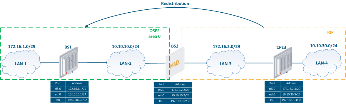 Image Removed Image Removed Image Added Image Added
Figure 2 - Scheme of the routes Route redistribution from RIP to OSPF |
Pre-configuration
| Description | Perform a devices preliminary configuration of the devices, consisting of the following steps: - Configure the device ID.
- Remove the svi1 interface.
- Assign IP addresses to the network interfaces, according to the scheme.
- Disable switching.
- Set Establish the wireless links.
|
|---|
| BS1 | | Code Block |
|---|
| Set the device ID
system prompt BS_1
Remove the svi1 interface
ifc svi1 destroy
Assign IP addresses
ifc eth0 10.10.10.1/24
ifc rf5.0 172.16.1.1/29
ifc lo0 192.168.0.1/32
Disable switching
switch stop
SetEstablish the radio link
rf rf5.0 band 20
rf rf5.0 freq 5100
mint rf5.0 -name "BS_1"
mint rf5.0 -type master |
|
|---|
| BS2 |
| Code Block |
|---|
| Set the device ID
system prompt BS_2
Remove the svi1 interface
ifc svi1 destroy
Assign IP addresses
ifc eth0 10.10.10.2/24
ifc rf5.0 172.16.2.2/29
ifc lo0 192.168.0.2/32
Disable switching
switch stop
SetEstablish the radio link
rf rf5.0 band 20
rf rf5.0 freq 5000
mint rf5.0 -name "BS_2"
mint rf5.0 -type master |
|
|---|
| CPE3 | | Code Block |
|---|
| Set the device ID
system prompt CPE_3
Remove the svi1 interface
ifc svi1 destroy
Assign IP addresses
ifc eth0 10.10.30.3/24
ifc rf5.0 172.16.2.3/29
ifc lo0 192.168.0.3/32
Disable switching
switch stop
SetEstablish the radio link
mint rf5.0 -name "CPE_3"
mint rf5.0 -type slave
mint rf5.0 prof 1 -band 20 -freq 5000 -type slave |
|
|---|
RIP configuration
| Description | Configure RIP on the BS2 and CPE3 devices. Step 1: Start RIP on the routers. Step 2: define the interfaces through which routing information should exchanged. |
|---|
| BS1 | No changes are required.
|
|---|
| BS2 | | Code Block |
|---|
| Start RIP:
arip start
Start RIP on the interfaces:
arip
config
router
network 172.16.2.0/29 |
|
|---|
| CPE3 | | Code Block |
|---|
| Start RIP:
arip start
Start RIP on the interfaces:
arip
config
router
network 10.10.30.0/24
network 172.16.2.0/29
network 192.168.0.3/32 |
|
|---|
OSPF protocol configuration
| Description | Configure the OSPF protocol in accordance with the scheme.: Step 1: start the OSPF daemon on the BS1 and BS2 routers. Step 2: set the routers IDs. The identifiers will be equal to the IP addresses assigned to the loopback interface. Step 3: define the interfaces where OSPF should be started. Step 4: redistribute the routes from the RIP protocol. Such routes have a "rip" type. Step 5: make announcement of advertise the directly connected networks on the BS2 router to announce the route to towards the BS2 loopback interface at BS1. |
|---|
| BS1 | | Code Block |
|---|
| Start OSPF:
ospf start
Set the router-id:
ospf
config
router
router-id 192.168.0.1
Start OSPF on the interfaces:
ospf
config
router
network 172.16.1.0/29 area 0.0.0.0
network 192.168.0.1/32 area 0.0.0.0
network 10.10.10.0/24 area 0.0.0.0 |
|
|---|
| BS2 | | Code Block |
|---|
| Start OSPF:
ospf start
Set the router-id:
ospf
config
router
router-id 192.168.0.2
Start OSPF on the interfaces:
ospf
config
router
network 10.10.10.0/24 area 0.0.0.0
Route redistribution from RIP:
ospf
config
router
redistribute rip
DirectlyAdvertise the directly connected networks announcement:
ospf
config
router
redistribute connected |
|
|---|
| CPE3 | No changes are required. |
|---|
Command output
...
analysis
Routing table
| Description | Analyze the routing table on each device. The routing tables of BS1 and BS2 are synchronized and contain entries that each device has information about each subnet shown in the scheme. This means that routes the route redistribution from RIP to OSPF were made was performed successfully. The CPE3's routing table consists of routes to the directly connected networks and a default route. This confirms the statement about the unidirectional redistribution. |
|---|
| BS1 | | Code Block |
|---|
| BS_1#1> netstat -r
Routing tables
Destination Gateway Flags Refs Use Interface
10.10.10.0/24 link#2 UC 0 0 eth0
10.10.30.0/24 10.10.10.2 UG3 0 0 eth0
127.0.0.1 127.0.0.1 UH 3 35 lo0
172.16.1.0/29 link#3 UC 0 0 rf5.0
172.16.2.0/29 10.10.10.2 UG3 0 0 eth0
192.168.0.1 192.168.0.1 UH 0 0 lo0
192.168.0.2 10.10.10.2 UGH3 0 0 eth0
192.168.0.3 10.10.10.2 UGH3 0 0 eth0
224.0.0.0/8 127.0.0.1 UGS 1 862 lo |
|
|---|
| BS2 | | Code Block |
|---|
| BS_2#1> netstat -r
Routing tables
Destination Gateway Flags Refs Use Interface
10.10.10.0/24 link#2 UC 0 0 eth0
10.10.30.0/24 172.16.2.3 UG3 0 0 rf5.0
127.0.0.1 127.0.0.1 UH 5 60 lo0
172.16.1.0/29 10.10.10.1 UG3 0 0 eth0
172.16.2.0/29 link#3 UC 0 0 rf5.0
192.168.0.1 10.10.10.1 UGH3 0 0 eth0
192.168.0.2 192.168.0.2 UH 0 0 lo0
192.168.0.3 172.16.2.3 UGH3 0 0 rf5.0
224.0.0.0/8 127.0.0.1 UGS 1 462 lo |
|
|---|
| CPE3 | | Code Block |
|---|
| AS_3#1> netstat -r
Routing tables
Destination Gateway Flags Refs Use Interface
10.10.30.0/24 link#2 UC 0 0 eth0
127.0.0.1 127.0.0.1 UH 3 60 lo0
172.16.2.0/29 link#3 UC 0 0 rf5.0
192.168.0.3 192.168.0.3 UH 0 0 lo0
224.0.0.0/8 127.0.0.1 UGS 0 91 lo |
|
|---|
Additional materials
Webinars
- Typical scenario of routing setting using Infinet Wireless devices. Part I.
- Typical scenario of routing setting using Infinet Wireless devices. Part II
Other
- Ifconfig command (interfaces configuration)
- mint command (MINT version)
- mint command (TDMA version)
- ARDA (Aqua Router Daemon)
- OSPF command
- arip command