...
The surface on which the devices is installed must support the outdoor unit device and power adapter weight. There must be enough space around the outdoor unit device for ventilation air flow and free access to the cable connectors: at least 15 cm on the side of the power adapter connection, cables and ventilation fins, and 5 cm on the other two sides. The operating temperature and humidity values must be within the permissible limits at the installation site of the device.
Desktop installation
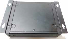
When installing the outdoor unit device on a table or any surface to prevent moving, it is recommended to use mounted headers supplied by default.
Wall installation
The outdoor unit device can be mounted on the wall by using optional wallmounting brackets (is not supplied by default). In order to install on the wall the following must be performed:
- Prepare wallmountig brackets.
- Align the brackets on each screw hole on the bottom of the outdoor unitdevice.
- Insert screws to secure the brackets.
- Place the outdoor unit device on where it will be mounted on the wall. You may draw marks for the circled screw holes for applying wall anchors in later steps. Do the same for both sides.
- Apply the 4 wall anchors designated in the last step. You must have a drilling machine to perform this step. Then, insert threaded nails into the anchors. Do NOT insert the nails totally into the anchor. Leave a tiny gap enough to hang the wallmounting bracket.
- Hang the outdoor unit device onto the wall. Remember to match the brackets’ 4 screw holes with the 4 threaded nails on the wall. You may screw the nails tighter after you hang the outdoor unitdevice.
Rack installation
The outdoor unit device can be mounted on a rack using L-shaped rackmounting brackets (is not supplied by default). Before installation please read the precautions first.
- Elevated Operating Ambient. If installed in a closed or multi-unit rack assembly, the operating ambient temperature of the rack environment may be greater than room ambient. Therefore, consideration should be given to installing the equipment in an environment compatible with the maximum ambient temperature specified by the manufacturer.
- Reduced Air Flow. Installation of the equipment in a rack should be such that the amount of air flow required for safe operation of the equipment is not compromised. Mechanical Loading: mounting of the equipment in the rack should be such that a hazardous condition is not created due to uneven mechanical loading.
- Circuit Overloading. Consideration should be given to the connection of the equipment to the supply circuit and the effect that overloading of the circuits might have on over-current protection and supply wiring. Appropriate consideration of equipment nameplate ratings should be used when addressing this concern.
- Reliable Grounding. Reliable grounding of rack-mounted equipment should be maintained. Particular attention should be given to supply connections other than direct connections to the branch circuit.
| Note | ||
|---|---|---|
| ||
Slide/rail mounted equipment is not to be used as a shelf or a work space. |
After reading the precautions, please see the following for mounting on a rack:
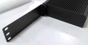
- Prepare the L-shaped rackmounting brackets.
- Attach the L-shaped brackets to the screw holes on eachside of the device. Apply screws to secure the brackets until totally fixed.
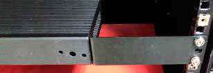
- Attach the ears of the L-shaped brackets to the rack and then apply long threaded nails. Repeat this for another side.
Power adapter connection
The InfiMUX 6G can be connected to the power adapter with a voltage of 100 ... 240 V with a frequency of 50 ... 60 Hz. After switching on, the power indicator on the outdoor unit device should turn green. In the event of a power failure, the device must be switched off. After the power is restored, turn it on again.
...
The PC can be connected to the first Ethernet port with an FTP Cat5e cable, or to the terminal console port with a console cable. The Infinet devices can be connected to the Ethernet ports with an FTP Cat5e cables.