...
Front Panel Features
Rear Panel Features
Interfaces
...
...
| macroId | 5fe022a8-a11b-4a43-b302-6d501d056fa1 |
|---|
| displayName | InfiMUX Overview |
|---|
| name | InfiMUX Overview |
|---|
| pagePin | 2 |
|---|
| name | InfiMUX Overview |
|---|
| pagePin | 4 |
|---|
|
- Console port - RJ-45 console port to connect to a computer terminal for diagnostic or configuration purpose.
Rear Panel Features
- Reset switch - can be used to reboot the system without turning off the powe
LEDs
LED indicators include SSD, Status, Power and Link/Activity indicators:
- SSD - the hard disk data reading indicator, if installed.
- Status - status indicator.
- Power - power indicator. Working condition: green - normal, red-fault.
- Link/Activity - the indicator is located in the bottom row of all Ethernet ports. The indicator lights in yellow if a connection is established and flashes when data is received or transmitted.
Motherboard block diagram
The block diagram depicts the relationships among the interfaces or modules on the motherboard. Please refer to the following figure for your motherboard’s layout design.
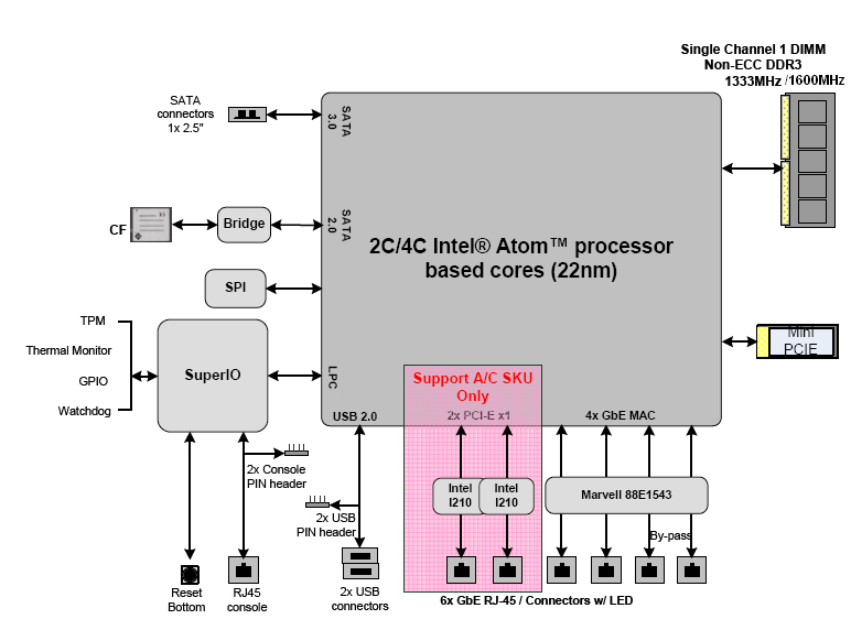 Image Added