Successfully pass the free certification exam at IW Academy and become an Infinet Certified Engineer.
CAUTION
Configurations from the scenarios below are examples that demonstrate the potential capabilities of the Infinet Wireless devices. The configurations may vary depending on the model and firmware version. We do not recommend copying this solutions to the hardware without checking.
Description
Quanta 5, Quanta 6 and Quanta 70 devices do not have software functionality for redundant links. However, you can create two redundant links on them with using third-party devices based on public technologies.
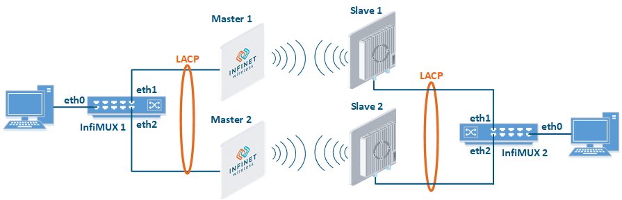
The simplest scheme will be the organization of two links established at the 2 level of OSI via two Quanta 5, Quanta 6 or Quanta 70 devices. LACP protocol excludes loops and allows to increase throughput.
In this case, the link aggregation is configured on the switches using the LACP protocol. These can be both InfiMUX switches or third-party equipment. Traffic will be balanced between the two links, increasing their total throughput, if one of them is breaking up, traffic will be completely transferred to the second link.
Unfortunately, in this case, the use of one frequency for two pairs of devices is not desirable.
Configuration Example
Step 1: Configure Master 1 and Slave 1 devices as the first radio link using the following parameters:
- Downlink center frequency: 5055 MHz;
- Uplink center frequency: 5055 MHz (Master only);
- Channel width: 40 MHz;
- Frame length: 5ms;
- Access key: 9876.
Step 2: Configure Master 2 and Slave 2 as the second radio link using the following parameters:
- Downlink center frequency: 5155 MHz;
- Uplink center frequency: 5155 MHz (Master only);
- Channel width: 40 MHz;
- Frame length: 5ms;
- Access key: 6789.
Step 3a: Configure LACP on the InfiMUX switches.
InfiMUX 1 / InfiMUX 2lag 0 port eth1 eth2 ifc lag0 up switch group 1 add eth0 lag0 switch group 1 start
- Step 3b: Configure LACP on the third-party equipment (not included in the example).