Successfully pass the free certification exam at IW Academy and become an Infinet Certified Engineer.
This section describes factors to be considered when planning the proposed link end sites, including grounding, lightning protection and equipment location for the wireless device, power supply, AUX-ODU-LPU-L and AUX-ODU-LPU-G unit (if installed).
CAUTION
Electro-magnetic discharge (lightning) damage is not covered under warranty. The recommendations in this document, when followed correctly, give the user the best protection from the harmful effects of EMD. However 100% protection is neither implied nor possible.
Grounding and lightning protection recommendations
- The wireless device should be placed on the pole at a height that is at least 1 meter below the top of the pole. In this case, there is a significant probability that the lightning strikes the pole and not the wireless device. The pole should be properly grounded: connected to the building lightning protection circuit according to your local regulations.
- All equipment must be connected at stabilized and surge protected power sources which must be properly grounded.
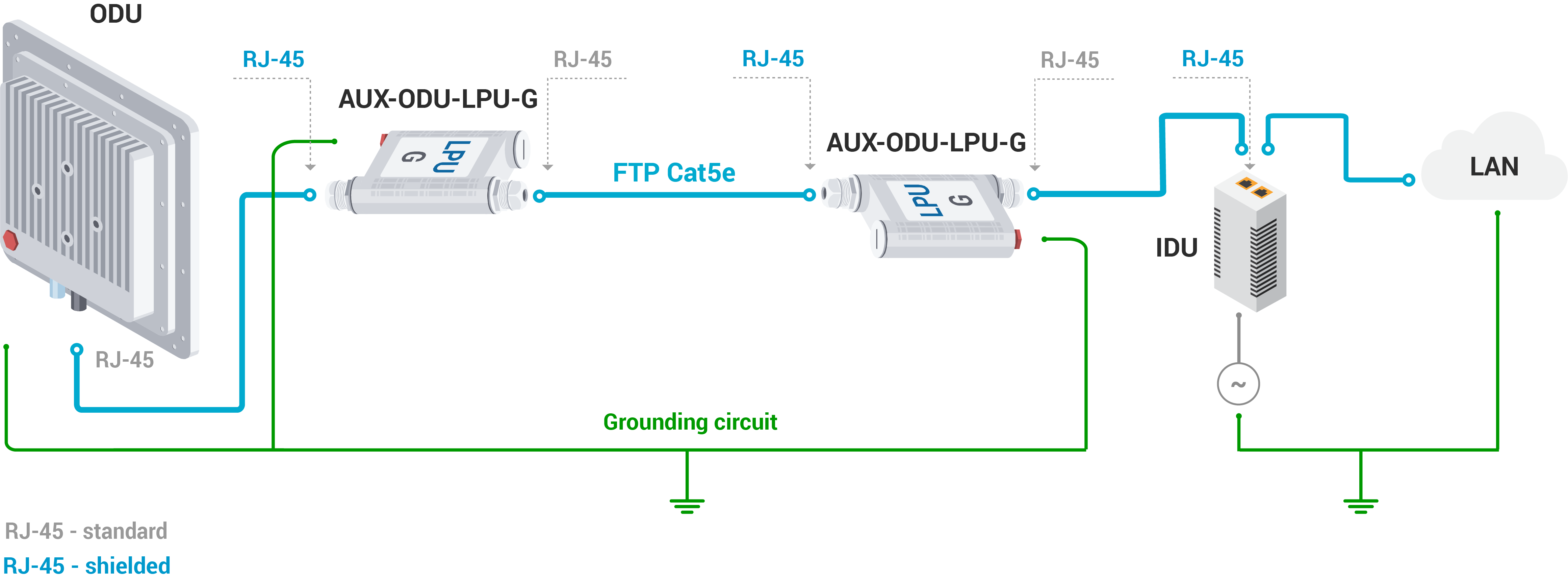
- The end of the FTP service cable that is connected to the power supply should be assembled with a shielded RJ-45 connector. The other end of the FTP service cable (connected to the wireless device) should be assembled with unshielded (standard) RJ-45 connector.
- The power supply is grounded via a three-conductor power cord and a grounded socket.
- AUX-ODU-LPU-L, AUX-ODU-LPU-G and wireless device grounding is performed using grounding bolt.
- Antenna pole and wireless device should be connected to the common ground ring. Grounding cables should be no less than 10AWG thick and must use corrosion-resistant connectors. An M5x10 grounding bolt is included in the supply list.
Requirements to the lightning protection unit AUX-ODU-LPU-L location
AUX-ODU-LPU-L is an optional accessory which may be used to serve as a line protection unit for the ODU and for the indoor network equipment connected to the Ethernet port of the IDU. AUX-ODU-LPU-L should be properly assembled, mounted and grounded.
General recommendations for installations of lightning protection units:
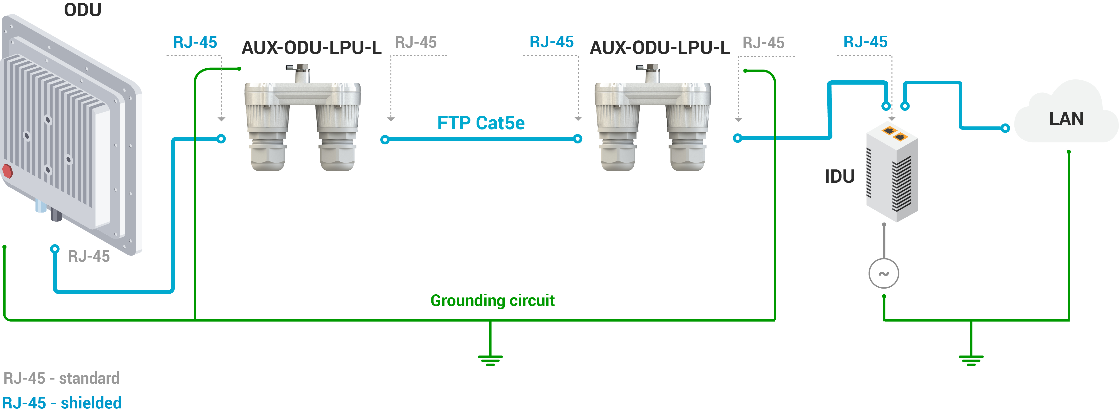
- Install the lightning protection unit on both ends of the cable to protect both the outdoor and the indoor unit. The purpose of the LPU at the top is to protect the ODU from a surge of lightning strike which can hit the long FTP cable run along the height of the pole or on the roof of the building. The purpose of the LPU at the bottom is to protect the IDU and customer equipment.
- Use the lightning protection unit to protect all circuits for signal transmission and power supply (video, audio, management signals, Ethernet, etc.)
- Regularly (especially before the periods with high thunderstorm activity) check the integrity of lightning protection units, grounding elements and bonding conductors.
- The ports of the AUX-ODU-LPU-L device are symmetrical, i.e. the correspondence of ports position to the external unit and the power supply does not matter.
Make sure to install the two LPU devices as shown in the scheme below.
CAUTION
Please note grounding cables should not be connected to the mast. All devices must use separate grounding cable that should be connected to the grounding circuit. The best scenario is when grounding cables are lined parallel to the Ethernet cable.
AUX-ODU-LPU-L Mounting
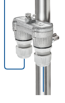
AUX-ODU-LPU-L is installed on a mast, using clamp. Attach the grounding cable (min cross-section 2.5 mm2) to the case, using grounding bolt. An M6x10 grounding bolt is included in the supply list.
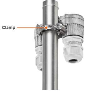
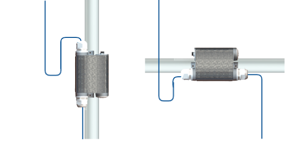
During AUX-ODU-LPU-L mounting it is necessary to provide a small loop of the FTP cable that should be below the cable gland. This ensures that water is not constantly channeled towards the connector. It will also serve as a cable compensation for the cable linear expansion as the temperature difference result.
CAUTION
Missing or bad grounding may leave the unit vulnerable to lightning damage.
AUX-ODU-LPU-L Cable Ggland Assembly
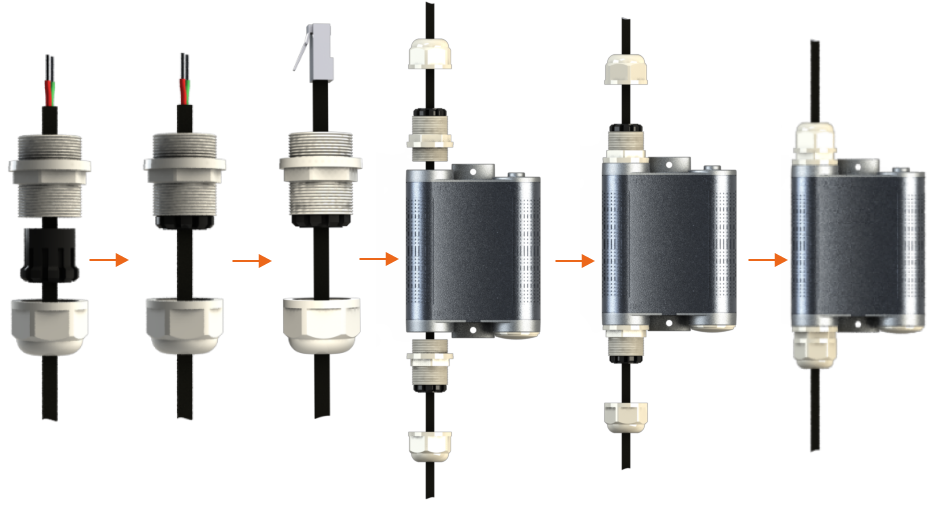
In order to ensure that the cable gland remains sealed under any environmental conditions, please, follow the assembly sequence according to the procedure below:
- Step 1: Insert the sealing insert into the clamping claw.
- Step 2: Assemble the cable gland by putting the thread-lock sealing nut, clamping claw with sealing insert and body onto the cable as shown on the figure.
- Step 3: Insert the clamping claw with sealing insert into the body as shown on the figure.
- Step 4: Crimp the standard RJ-45 connector onto the cable using crimping tool. Pin-out scheme: T568B wiring standards.
CAUTION
Make sure that the RJ-45 connector is well-crimped. A loose connector can damage the device. Please note that such damage is not covered by the warranty.
- Step 5: Insert the RJ-45 connector into the corresponding socket until you hear a click.
- Step 6: Screw the cable gland body into the port and tighten it. Do not apply excessive force.
- Step 7: Tighten the thread-lock sealing nut. Do not apply excessive force.
Requirements to the lightning protection unit AUX-ODU-LPU-G location
AUX-ODU-LPU-G is an optional accessory which may be used to serve as a line protection unit for the ODU and for the indoor network equipment connected to the Ethernet port of the IDU.
AUX-ODU-LPU-G should be properly assembled, mounted and grounded.
General recommendations for installations of lightning protection units:
- Install the lightning protection unit on both ends of the cable to protect both the outdoor and the indoor unit. The purpose of the LPU at the top is to protect the ODU from a surge of lightning strike which can hit the long FTP cable run along the height of the pole or on the roof of the building. The purpose of the LPU at the bottom is to protect the IDU and customer equipment.
- Use the lightning protection unit to protect all circuits for signal transmission and power supply (video, audio, management signals, Ethernet, etc.)
- Regularly (especially before the periods with high thunderstorm activity) check the integrity of lightning protection units, grounding elements and bonding conductors.
Make sure to install the two LPU devices as shown in the scheme below. The ports connection order does not matter for LPU.
CAUTION
Please note grounding cables should not be connected to the mast. All devices must use separate grounding cable that should be connected to the grounding circuit. The best scenario is when grounding cables are lined parallel to the Ethernet cable.
AUX-ODU-LPU-G Mounting
AUX-ODU-LPU-G can be installed on a pole, using hose clamps. Attach the grounding cable (min cross-section 2.5 mm2) to the case, using grounding bolt. An M6x10 grounding bolt is included in the supply list.
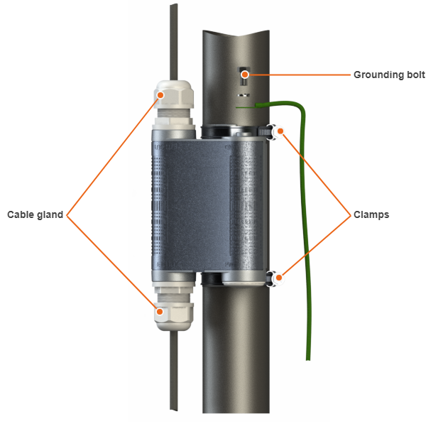
During AUX-ODU-LPU-G mounting it is necessary to provide a small loop of the FTP Cat5e cable that should be below the cable gland. These ensure that water is not constantly channeled towards the connectors. It will also serve as a cable compensator for the cable linear expansion as the temperature difference result.
CAUTION
Missing or bad grounding may leave the unit vulnerable to lightning damage.
AUX-ODU-LPU-G Cable Gland Assembly
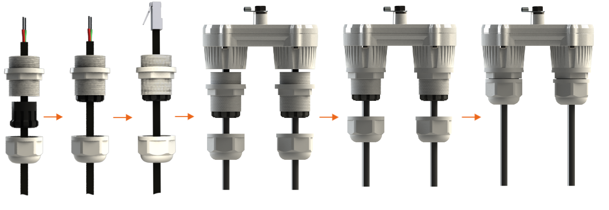
In order to ensure that the cable gland remains sealed under any environmental conditions, please, follow the assembly sequence according to the procedure below:
- Step 1: Insert the sealing insert into the clamping claw.
- Step 2: Assemble the cable gland by putting the thread-lock sealing nut, clamping claw with sealing insert and body onto the cable as shown on the figure.
- Step 3: Insert the clamping claw with sealing insert into the body as shown on the figure.
- Step 4: Crimp the standard RJ-45 connector onto the cable using crimping tool. Pin-out scheme: T568B wiring standards.
CAUTION
Make sure that the RJ-45 connector is well-crimped. A loose connector can damage the device. Please note that such damage is not covered by the warranty.
- Step 5: Insert the Rj-45 connector into the corresponding socket until you hear a click.
- Step 6: Screw the cable gland body into the port and tighten it. Do not apply excessive force.
- Step 7: Tighten the thread-lock sealing nut. Do not apply excessive force.