AUX-ODU-LPU-G is an optional accessory which may be used to serve as a line protection unit for the ODU and for the indoor network equipment connected to the Ethernet port of the IDU.
AUX-ODU-LPU-G should be properly assembled, mounted and grounded.
General recommendations for installations of lightning protection units:
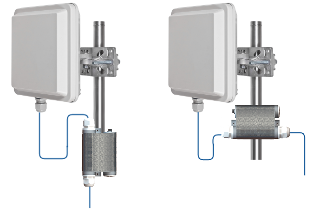
- Install the lightning protection unit on both ends of the cable to protect both the outdoor and the indoor unit. The purpose of the LPU at the top is to protect the ODU from a surge of lightning strike which can hit the long FTP cable run along the height of the pole or on the roof of the building. The purpose of the LPU at the bottom is to protect the IDU and customer equipment.
- Use the lightning protection unit to protect all circuits for signal transmission and power supply (video, audio, management signals, Ethernet, etc.)
- Regularly (especially before the periods with high thunderstorm activity) check the integrity of lightning protection units, grounding elements and bonding conductors.
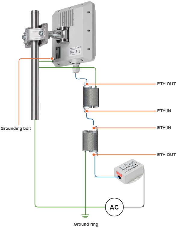
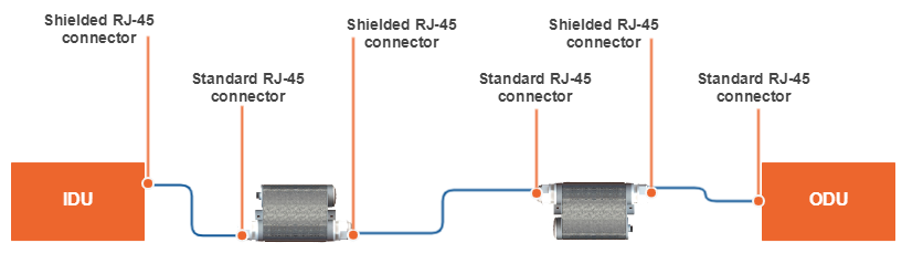
Make sure to install the two LPU devices in the correct polarity, as shown in the diagram:
- Top LPU with "ETH OUT" facing the ODU.
- Bottom LPU with "ETH OUT" facing the IDU.
- LPU units connected to each other via "ETH IN".
AUX-ODU-LPU-G Mounting
AUX-ODU-LPU-G can be installed on a pole, using hose clamps. Attach the grounding cable (min cross-section 2.5 mm2) to the case, using grounding bolt.
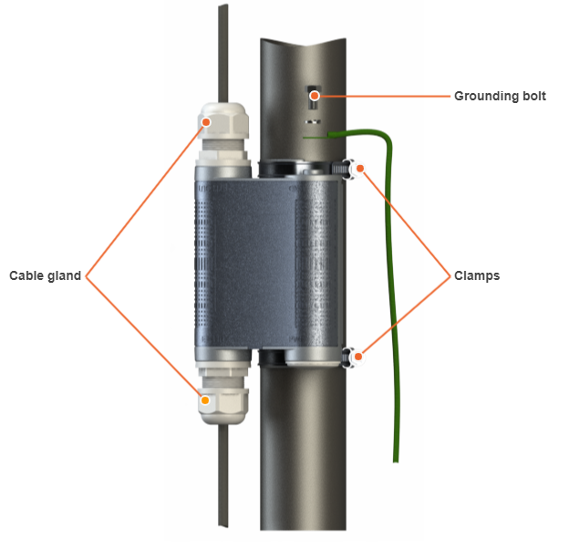
During AUX-ODU-LPU-G mounting it is necessary to provide a small loop of the FTP Cat5e cable that should be below the cable gland. These ensure that water is not constantly channeled towards the connectors. It will also serve as a cable compensator for the cable linear expansion as the temperature difference result.
CAUTION
Missing or bad grounding may leave the unit vulnerable to lightning damage.
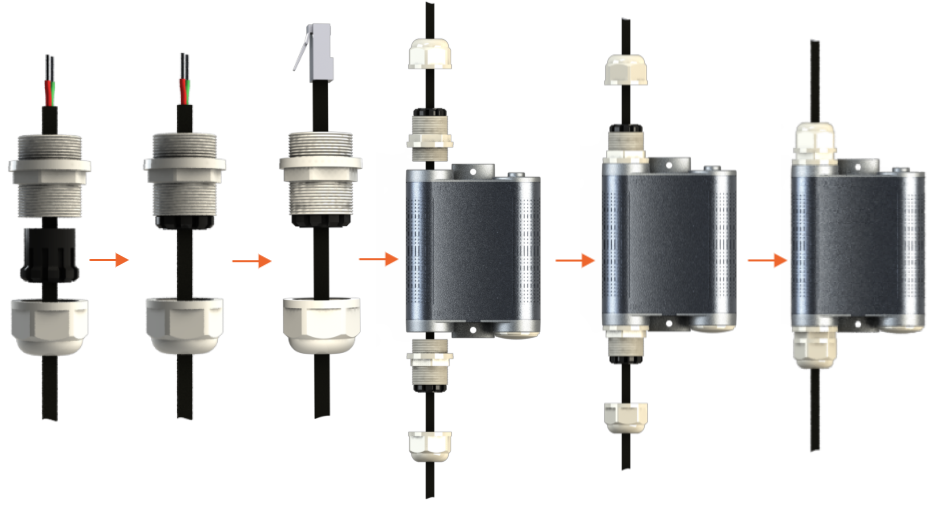
AUX-ODU-LPU-G Cable Ggland Assembly
In order to ensure that the cable gland remains sealed under any environmental conditions, please, follow the assembly sequence according to the procedure below:
- Step 1: Insert the sealing insert into the clamping claw.
- Step 2: Assemble the cable gland by putting the thread-lock sealing nut, clamping claw with sealing insert and body onto the cable as shown on the figure.
- Step 3: Insert the clamping claw with sealing insert into the body as shown on the figure.
- Step 4: Crimp the standard RJ-45 connector onto the cable using crimping tool. Pin-out scheme: T568B wiring standards.
CAUTION
Make sure that the RJ-45 connector is well-crimped. A loose connector can damage the device. Please note that such damage is not covered by the warranty.
NOTE
For connection to "ETH IN" terminate the cable with the standard RJ-45 connector (4) according to the EIA/TIA-568B.
For connection to "ETH OUT" terminate the cable with the shielded RJ45 connector (5) according to the EIA/TIA-568B (to provide grounding circuit).
- Step 5: Insert the Rj-45 connector into the corresponding socket until you hear a click.
- Step 6: Screw the cable gland body into the port and tighten it. Do not apply excessive force.
- Step 7: Tighten the thread-lock sealing nut. Do not apply excessive force.