Successfully pass the free certification exam at IW Academy and become an Infinet Certified Engineer.
In order to setup an operational point-to-point link please follow the steps below.
Perform site survey
- Use InfiNet Wireless link planner tool InfiPLANNER to estimate link performance and required configuration in terms of antennas, channel width, Tx power, etc.
- Determine line of sight conditions and obstacles along the path
- Perform spectrum analysis and figure out spectrum occupation and available channels
Pre-configure units in the lab
The equipment list required for lab configuration
| Component | Description |
|---|---|
|
|
|
|
|
|
|
|
|
|

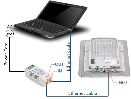
In the lab and later on site connect the devices as indicated below:
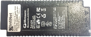
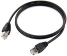
- Connect laptop to the IDU port labeled as "IN" with an Ethernet cable.
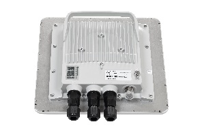
Use another Ethernet cable to connect "GE0" port at the ODU to the IDU port labeled as "OUT".
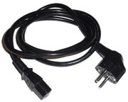
- Use power cord to connect the IDU using AC mains.
CAUTION
Before supplying power to the Um models an external antenna or RF terminators with 50 Ohms resistance must be connected to both N-type connectors.
During laboratory testing, it is allowed to directly connect two devices with RF cables without antennas with the mandatory use of attenuators with attenuation of at least 40 dB for each polarization. Switching off/on the attenuators and RF cables should only be performed when the devices are in the off state.
In case the antenna, attenuator or terminator is connected to only one N-type connector do not switch on the device.
PLEASE NOTE THAT VIOLATION OF THE ABOVE REQUIREMENTS VOIDS THE WARRANTY.
After the physical connections are completed, configure each unit as described below.
Units settings can be performed via:
Settings via web interface
| Step 1 |
|---|
Access the unit to the default IP address 10.10.10.1 with mask 255.255.255.0 via web browser. Make sure that the Ethernet port of the Laptop has an IP address assigned from the same subnetwork as the one for the unit (for example, set 10.10.10.50 with mask 255.255.255.0). |
| Step 2 |
Use any letters or numbers for initial authentication, for example:
NOTE Make sure to set strong passwords before running the units in production. |
| Step 3 |
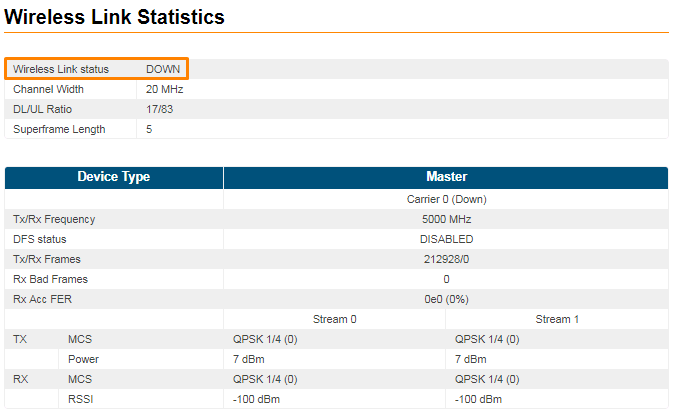
Log in to the Web GUI. Initially the status of the radio link is DOWN like below. Figure - Initial link status |
| Step 4 |
Upgrade the units to the latest stable firmware version. For more details go to the section "Maintenance". |
| Step 5 |
Perform radio settings. Go to the "Radio" section and set the following parameters:
NOTE The detailed description for each radio setting can be found in the section "Radio". CAUTION Please note that the following parameters must have the same values at each of the two units in the PtP link. Otherwise the wireless link won’t be established:
|
| Step 6 |
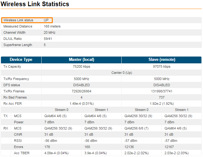
Save the configuration, reboot both units and check if they link is up. The link status should be UP and the radio statistics should indicate the capabilities and quality of the link.
Figure - Link UP status |
Settings via CLI
| Step 1 | |||||||||||||||||||||||||||
|---|---|---|---|---|---|---|---|---|---|---|---|---|---|---|---|---|---|---|---|---|---|---|---|---|---|---|---|
CLI is available via telnet: "cmd> telnet 10.10.10.1" or use any suitable telnet client such as Putty. 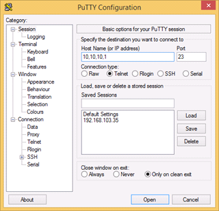 | |||||||||||||||||||||||||||
| Step 2 | |||||||||||||||||||||||||||
Use any letters or numbers for initial authentication, for example:
NOTE Make sure to set strong passwords before running the units in production. | |||||||||||||||||||||||||||
| Step 3 | |||||||||||||||||||||||||||
Check the firmware version and upgrade the units to the latest stable firmware version. You can check firmware version via command: xginfo version Compare current version of the unit with version on official Infinet ftp server: https://ftp.infinet.ru/pub/Firmware/XG/. In case a newer version is available we recommend upgrading. For more details go to the section "Maintenance". | |||||||||||||||||||||||||||
| Step 4 | |||||||||||||||||||||||||||
Configure radio parameters.
NOTE Commands description is given in the section "Commands for modem configuration". CAUTION Please note that the following parameters must match at both units. Otherwise the wireless link won’t be established:
NOTE In order to apply the same settings to the another unit you should use the following command output "xg config -peer-exported". Execute these commands in CLI of the another unit. #Peer exported config: xg -v3-start xg -v3 a01b833402f59907abdcb812d5de20fd.Ko7ClHTRVps/8oyNjnucBcSqUlcCJbOae9Kf4OZ xg -v3 zRU7tYm1REMTUyHWYTaGGuuooDp2DWkcxyFGLmEb5yx45wFImL5Nx72XK6bnl9AzRdZjWVSN xg -v3 xCrliSUfn7JZazn1yTEKE90fKLIK/HKNJXYN7vg4lEocgBWguYdFc/u8fEwENtJYBSKNGbu3 xg -v3 HQ0HvIdTqAwOz5vXM89CkhL5ZZmDuYN3FFSo6wV+h//zBuSfuJ5QVb6fv2Do6tPIE4kuZSsB xg -v3 UXLavUriPtSlRxzIYUO7+9XSMggomrf7NZtM37PxQkUYIZ116K3++w5HPVXXq8Po7xVmotnq xg -v3 px1uDbYtSjs2O9yx6h6Z0HGp8GLAEY7Ka5ZRoyAvyfA73pobYrEhzZ+hdwWnDDJYM3DmAhuW xg -v3 yAUgtVHJ4hC9u6BP5IAlQXsm5QSbuRwihWdmrwiThwSGmXiZWCXOmxzg1IA== xg -v3-end | |||||||||||||||||||||||||||
| Step 5 | |||||||||||||||||||||||||||
Save configuration. config save | |||||||||||||||||||||||||||
| Step 6 | |||||||||||||||||||||||||||
Restart the unit. restart yes | |||||||||||||||||||||||||||
| Step 7 | |||||||||||||||||||||||||||
Check the link status. Sys log show | grep UP In case of success configuration: [XG]: changed state UP->DOWN |
Perform Initial Antenna Alignment
| Step 1 | |||||||||||||||||||||
|---|---|---|---|---|---|---|---|---|---|---|---|---|---|---|---|---|---|---|---|---|---|
Install both units on the pole and direct them at each other (more detailed information about units installation and antenna alignment is described in the section "Units Installing"). | |||||||||||||||||||||
| Step 2 | |||||||||||||||||||||
Turn them on and make sure that the units subsystems are working properly. This can be done by LED indication. 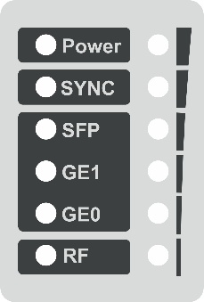
Table - Indicator Panel Description | |||||||||||||||||||||
| Step 3 | |||||||||||||||||||||
Perform coarse alignment using built-in signal strength indicators. NOTE The more indicators are on, the better wireless connection is established. The blinking indicator means an intermediate state. The more often the indicator blinks the higher level connection is established. | |||||||||||||||||||||
| Step 4 | |||||||||||||||||||||
Perform fine alignment using the "Alignment tool" available in the Web interface or "xginfo stat" output in the CLI. Try to maximize CINR and RSSI readings. Please follow the detailed indications from section Antenna alignment for a proper antenna alignment. |
Optimize the Link Performance
| Method 1 | ||||||||||
|---|---|---|---|---|---|---|---|---|---|---|
Depending on the values for CINR, RSSI change the following parameters:
| ||||||||||
| Method 2 | ||||||||||
Use the Spectrum Analyzer tool built-in the Web GUI in order to determine the best frequency and to check the radiation levels in the installation area. Frequency should be left to "auto" in case of Instant DFS units (for unlicensed bands), or it should be set to a specific value (in countries where DFS is not mandatory) on the master unit after performing the Spectrum Analyzing test on both units. | ||||||||||
| Method 3 | ||||||||||
Select the most appropriate air frame period:
| ||||||||||
| Method 4 | ||||||||||
| Enable "Short Cyclic Prefix" mode in order to mitigate inter-symbol interference due to multipath propagation environment. | ||||||||||
| Method 5 | ||||||||||
| Enable "Control Block Boost" mode that improves link availability in the most difficult propagation and interference conditions due to the radio frame with control information transfer at duplicate transmit power. | ||||||||||
| Method 6 | ||||||||||
| Enable "Instant DFS" that gives availability to change frequency without link interruption. | ||||||||||
| Method 7 | ||||||||||
Monitor air block error rate by checking the "Acc TBER" parameter in the "Status" page or in "xginfo stat" output and adjust the AMC strategy if necessary. NOTE Acceptable error rate depends on the application. See some examples in the table below.
Table - Acceptable error rates for different applications The "AMC Stratefy" may be changed depending on customer erquirements:
It is recommended to use “normal” strategy initially and adjust it based on target and actual TBER values. |