Table of contents
Introduction
The data networks evolution entails an increase in the volume of transmitted traffic, which requires the quality of service policy usage. The policy implementation will allow classifying network traffic and distributing network resources between traffic classes.
Terminology
- QoS (Quality of Service) - technology that allows to classify a data stream and prioritize the each stream transmission in accordance with its class.
- QoS policy - document describing the principles of traffic streams classification and resource requirements for each class.
- Traffic stream - data of one service transmitted between two nodes.
- Service - process running on end nodes which data need to be transmitted between nodes. Data of one service is distinguished by a unique set of service field values and the network packets structure. IP telephony, web, and video surveillance are the examples of services.
- Responsibility area - a network segment which effective operation is in responsibility of a certain subject. A subject can be either a specific person or an organization.
- DS domain (Differentiated Services domain) - a logical area having uniform traffic classification rules defined by QoS policy. Usually the DS domain coincides with responsibility area.
- CIR - Committed Information Rate. The system guarantees the resources allocation in compliance with the CIR for the service.
- MIR - Maximum Information Rate. In case CIR is ensured, the additional resources may be allocated to the services. Additional resources cannot exceed the MIR threshold and their allocation is not guaranteed.
Package distribution scheme
In packet networks traffic is transmitted from the sending node to the receiving node through communication channels and intermediate devices. Generally a data packet is processed by each intermediate device independently. Let's look at the example of a data packet processing by an intermediate network device (Figure 1):
- Node-2 forms a data packet and transmits it to Environment-2. The data packet is encapsulated in L2-protocol frame used in Environment-2.
- The data frame is distributed in Environment-2. The frame is converted into a modulated signal in accordance with an environment physical properties. Signals used in wired and wireless environments are different, which affects their propagation properties and usage scenarios.
- The signal arrives at the input device interface; after demodulation, the received data frame is checked for integrity: damaged frames are discarded.
- The next stage - routing determines frames further path. If the frame is addressed to a Network device, it is passed for processing to internal services. If the frame is addressed to another node, two scenarios are possible: the frame must be passed further through the output interface, or discarded (if Environment-2 is a common environment, where all signals will be received by all devices connected to the environment. In accordance with the L2 protocols operational principles, if the receiver address in the frame header does not belong to the device, then the device should discard it).
- In case the frame should be processed and transferred to another node, it enters the packets queue. A packets queue is a set of buffers that contain data received by incoming interfaces. The number and size of memory buffers for the packets queue storage are not standardized and depend on the equipment manufacturer. For example, the InfiLINK 2x2 devices family has 32 queues, 17 of which are available for configuration by user.
- The data frame passes through the packets queue to which it was placed, and enters the outgoing interface.
- Since packets queues are a link between incoming and outgoing interfaces, a device should have a controller that fills the queues with incoming data and picks data from the queues for transmission to outgoing interfaces. Usually, these functions are performed by the central processing unit (CPU). As will be shown below, the filling and picking data from queues can be performed unevenly and depend on the data streams classification.
- The outgoing interface generates a modulated signal and transmits it to Environment-5 with connected Node-5, which is the receiver of the original data frame.
- Node-5 receives a signal, demodulates it, and processes the received data frame.
Note, in the modern network devices, network interfaces mostly are combined and can operate as both incoming and outgoing.
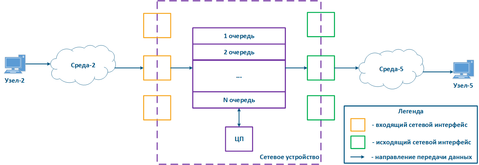
Figure 1 - A network device traffic passing scheme
A network device can be intermediate for several pairs of nodes, and each can transmit data of several services (Figure 2a). Let's look at the scheme there the Network device is intermediate for the traffic of nodes pairs Node-1 - Node-4, Node-2 - Node-5 and Node-3 - Node-6. The first pair transmits data of three services, the second of two, the third of one. If there are no QoS settings, the data of all services get through the general queue in the order they are received on the Network device and in the same order they will be transferred from the queue to outgoing interfaces.
With QoS configured, each of the incoming traffic flows can be classified by its type (for example) and map a separate queue to each class (Figure 2b). КEach packet queue can be assigned a priority, which will be taken into account during packets extraction from queues, and will guarantee quality indicators. The traffic flows classification can be performed not only by the services used, but according to other criteria. For example, each pair of nodes can be assigned a separate message queue (Figure 2c).
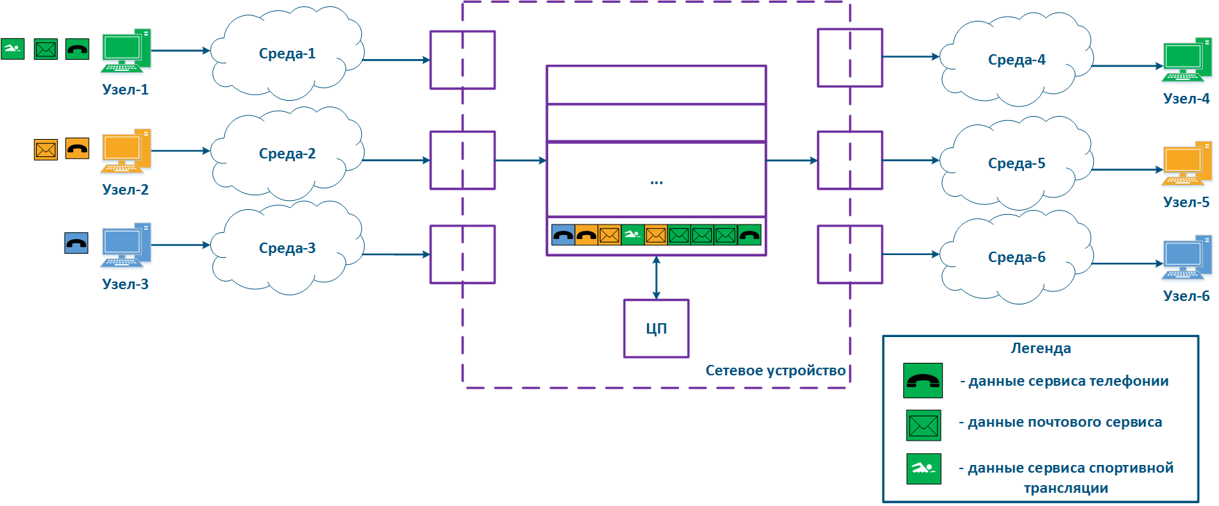
Figure 2a - Queuing for various services without QoS
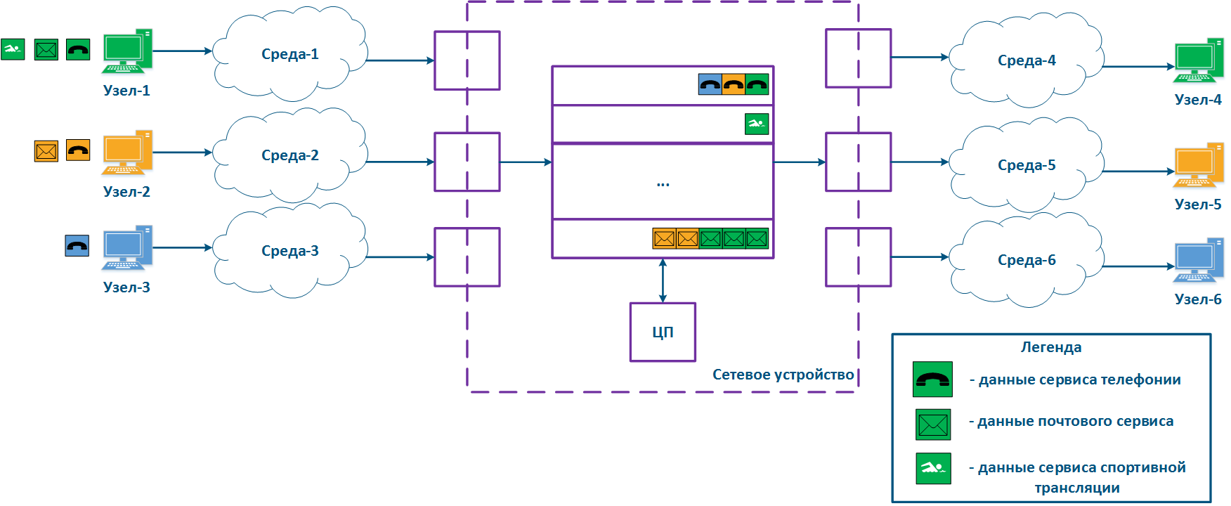
Figure 2b - Queuing for various services with QoS
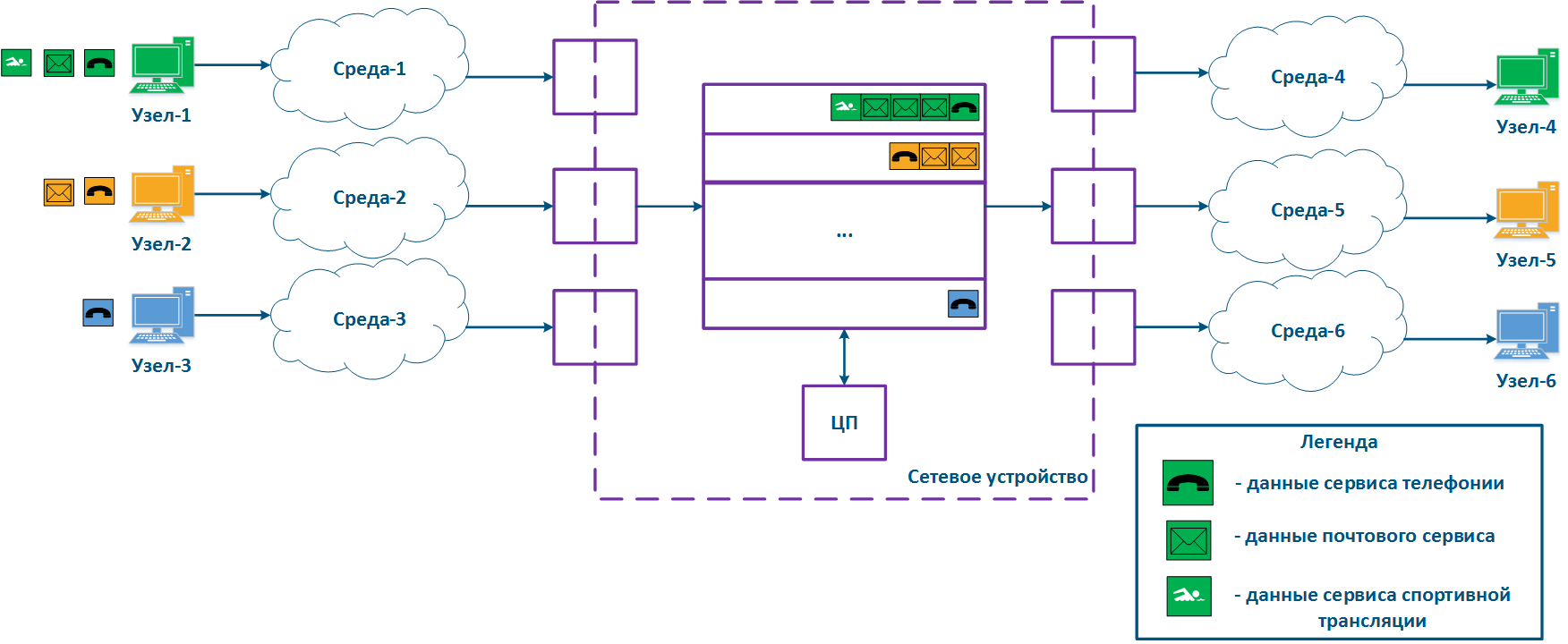
Figure 2b - Queuing for various users with QoS
Keep in mind that several intermediate network devices can be located on the data path between the source and the receiver, with independent packets queues on each, i.e. effective QoS policy implementation will require the configuration of all network nodes.
Quality indicators
The main conclusions from the previous section, which will be used to define quality metrics:
- The communication channel and network devices throughput is finite.
- The data delivery time from source to destination is non-zero.
- A communication channel is an environment with a set of physical parameters that define the signal propagation effects.
- The software and hardware network device architecture can affect the data distribution.
There are three main quality metrics:
- Losses.
- Delay.
- Jitter.
Let's look at the metrics on the example: Node-2 transmits three data packets to Node-5, the data source and recipient are connected to an intermediate Network device, the packets are transmitted within the same service, i.e. their key service fields are the same.
Losses
During a data stream transmission, some packets may not be received, or may be received with errors. This process is called as data loss, and is measured as the number of received packets to the number of transmit packets ratio. In the example (Figure 3), Node-2 transmits packets with identifiers 1,2 and 3, however, Node-5 receives only packets 1 and 3, i.e. packet with identifier 2 was lost. There are network mechanisms which allows retransmitting lost data. For example, such mechanisms are the TCP and ARQ protocols.
The causes of data loss can be divided into the following groups:
- Losses in medium: losses related with signal propagation in the physical environment. For example, the frame will be lost if the useful signal level is lower than the receiver sensitivity. Losses can also be caused by physical damage of the interfaces connected to the media or by impulse pickups resulting from poor grounding.
- Losses on the interface: losses during processing a queue on incoming or outgoing interface. Each interface has a memory buffer, which can be completely filled in case of intensive data stream. In this case, all subsequent data entering the interface will be discarded, because cannot be buffered.
- Losses in the device: Data discarded by the network device according with configuration logic. If the queues are full and the incoming data cannot be added to the processing queue, the network device will drop it. Also, these losses include data packets rejected by access lists and a firewall.
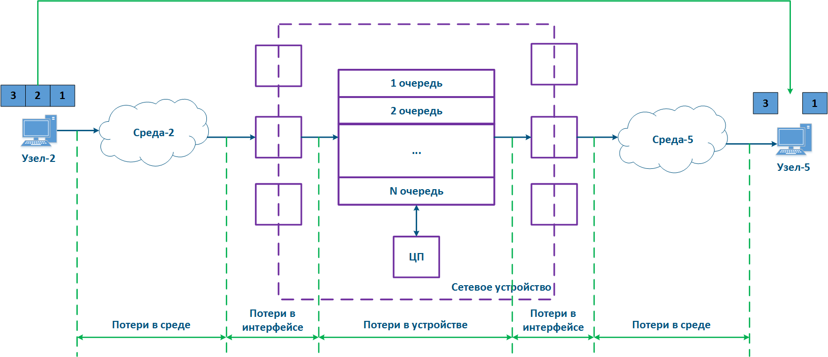
Figure 3 - Data packet loss example
Losses affect two indicators: throughput and packet performance, which are not belong to basic.
Throughput
One of the main indicator practically used is a throughput, which value depends on losses. Throughput is defined by the physical channel capabilities and by the intermediate network devices ability to process the data stream. The link throughput is defined as the maximum amount of data that can be transmitted from a source to a receiver per unit time.
Packet performance
The parameter that affects a throughput and the queues state is a packet performance of the device. Packet performance is a maximum data packets amount of a given length that a device is capable to transmit per unit of time.
A real throughput depends on both packet performance and interface characteristics, therefore, at the network design stage, pay attention to these parameters coherence so avoid the situation when one of them becomes a bottleneck for a link and network segment.
The packet performance is defined by the hardware capabilities of the central processor and the internal memory amount. Network devices process multiple traffic streams with different L2 frame sizes, so the following Ethernet frame size values are used for a performance testing:
- minimum size = 64 bytes;
- medium size = 512 bytes;
- maximum size = 1518 bytes.
Due to the limited internal memory amount, better packet performance is achieved for a minimum frame size. Minimal size frames using assume a large overhead amount: each data frames has an service header, which size does not depend on the size of the frame itself.
For example, the service header length for frames 64 bytes long (Figure 4b) and 156 bytes (Figure 4c) will be the same, but the user data amount will be different. To transmit 138 bytes of user data, three frames 64 bytes long or one frame 156 bytes long will be required, so in the first case 192 bytes are needed, in the second - 156 bytes. If link has the same throughput, large frames will increase efficiency by rising the useful throughput of the system. The Infinet devices performance values in various conditions is shown in the "Performance of the InfiNet Wireless devices" document.
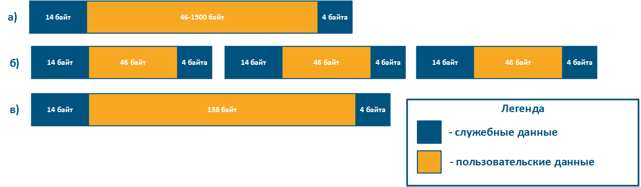
Figure 4 - Examples of various lengths Ethernet frame structure
Delay
Delay is the data packet transmission time from a source to a receiver. The delay value consists of the following parts:
- Signal propagation time in the medium: depends on the medium physical characteristics, is nonzero in any case.
- Serialization time: the conversion of a bitstream to a signal and backward by the incoming/outgoing interfaces is not instantaneous and requires hardware resources of a network device.
- Processing time: time the data packet spends is in the device. This time depends on the packet queues status, as a data packet will be processed only after processing packets placed in this queue earlier.
The delay is often measured, as a round-trip time (RTT), i.e. the time it takes for the data packet to be transmitted from a source to a destination and backward. For example, this value is used in the ping command results. The state of intermediate network devices during processing the data packets forward and backward may differ, therefore, usually the round-trip time is not equal to two one-way delays.
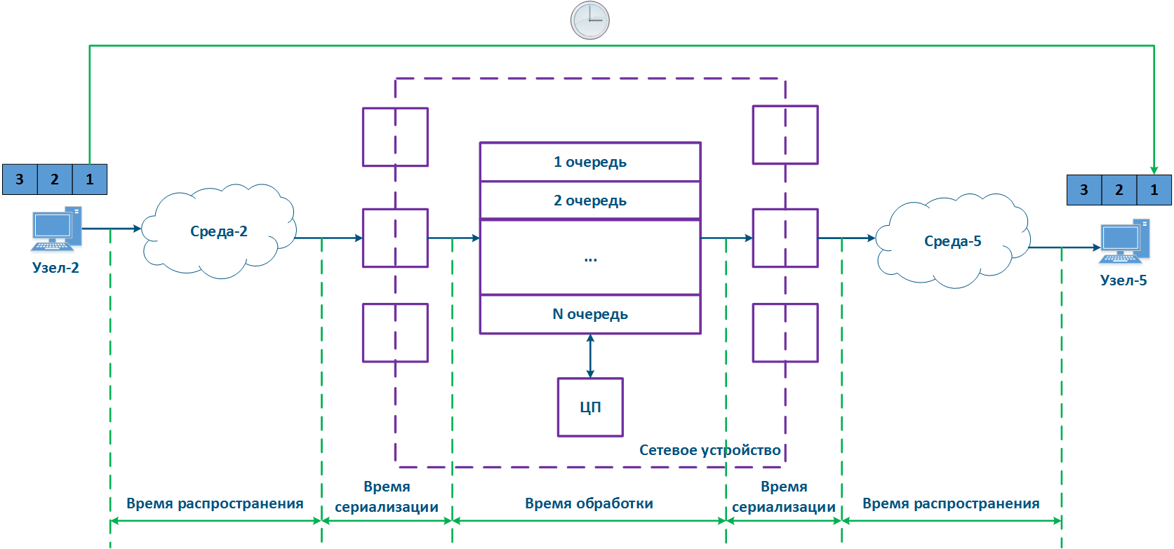
Figure 5 - Example of data transfer delay
Jitter
CPU loading and the packets queues status on intermediate network devices are frequently changing, so the delay during data packets transmission can change. In the example (Figure 6), the transmission time of packages with identifiers 1 and 2 is different. The difference between the maximum and average delay values is called jitter.

Figure 6 - Example of floating delay in data transfer
In a redundant network infrastructure data between the source and the receiver can be transmitted in various ways, it will also lead to the jitter appearance. Sometimes the difference between the delays in the link may become so large that the transmitted data packets order will change on the receiving side (Figure 7). In the example, packets with identifiers were received in a different order.
The effect depends on the service characteristics and the ability to restore the original sequence by higher levels network protocols. For example, if the traffic of different services is transmitted through different paths, then it will not affect the disorder of the received data.
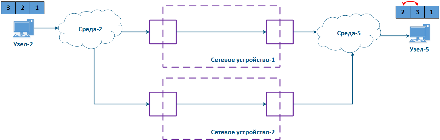
Figure 7 - Example of unordered data delivery
Services requirements for quality indicators
Each of the data transfer services has a requirements set for quality indicators. The RFC 4594 document includes the following service types:
| Service | Indicator | ||
|---|---|---|---|
| Losses | Delay | Jitter | |
| Network Control | low | low | low |
| Telephony | very low | very low | very low |
| Signaling | low | low | low |
| Multimedia Conferencing | medium | very low | low |
| Real-Time Interactive traffic | low | very low | low |
| Multimedia Streaming | medium | medium | low |
| Broadcast video | very low | medium | low |
| Low-Latency Data | low | medium | very low |
| Management | low | medium | medium |
| High-Throughput Data | low | high | high |
| Standard | undefined | ||
| Low-Priority Data | high | high | high |
QoS ensuring methods
The various services traffic transmission is performed on a single network infrastructure, which has limited resources, therefore, mechanisms should be provided for the resources distribution between services.
Let's look at the example (Figure 8), Node-2 generates several services traffic with a total speed of 1 Gbit/s, Environment-2 allows to transfer this data stream to an intermediate network device, however, the maximum link throughput between network device and Node-5 is 500 Mbps. Obviously, the data stream cannot be processed completely and part of this stream must be dropped. The QoS task is to make this drops manageable to provide the end services the required metric values. Of course, it is impossible to provide the required performance for all services, as links throughputs do not match, therefore, the QoS policy implementation involves that critical services traffic should be processed first.

Figure 8 - Example of inconsistency in incoming traffic amount and links throughputs
The example above allows shows two main methods used in the QoS policy implementation:
- Prioritization: data distribution among queues and packets selection from queues by priority. In this case, packets most sensitive to delay and jitter are processed first, then traffic, for which the delay value is not critical.
- Throughput limitation: throughput limitation for traffic flows. All traffic that exceeds the set throughput threshold will be discarded.
Let's look at the example above, and add the second intermediate device to the data distribution scheme (Figure 9a). The packets distribution scheme has the following steps:
- Step 1:
- Node-1 and Node-2 generate packets of two services: telephony and mail. The telephony traffic is sensitive to delay and jitter unlike mail service data (see Services requirements for quality indicators), therefore, it must be processed first by the intermediate devices.
- Network device-1 receives Node-1 and Node-2 packets.
- Step 2:
- Traffic prioritization is configured on Network device-1, thus the device classifies incoming traffic and places data packets in different queues. Whole telephony traffic will fall in queue 0, and mail traffic in queue 16. Thus, the queue 0 priority is higher than queue 16.
- Packets leave queues and proceed to outgoing interfaces in accordance with the queues priorities i.e. queue 0 will be emptied first, then queue 16.
- Step 3:
- Network device-1 sends data to Environment-7, connected with Network device-2. The data packets sequence corresponds to quality metrics - telephony data is transmitted to environment first, and the mail service next.
- Node-3 is connected to Network device-2 and generates a mail service data stream.
- Step 4:
- The Network Device-2 has no prioritization settings, thus all incoming traffic falls in the queue 16. Data will leave queues in the same order they entered, i.e. telephony and mail service traffics will be handled equally, despite the requirements for the quality indicators.
- Сетевое устройство-2 вносит задержку во время распространения трафика телефонии.
- Step 5:
- Data are transmitted to the end nodes. The telephony packets transmission time was increased due to the Node-3 mail service traffic processing.
Each intermediate network device without traffic prioritization settings will increase the data transmission delay, and the delay amount is unpredictable. Thus, a large number of intermediate devices will make real-time services operation impossible because of the quality indicators unattainability, i.e. traffic prioritization must be done along the entire network traffic transmission path (Figure 9b).
Keep in mind that implementing QoS policies is only one component to ensure quality metrics. For maximum effect, the QoS configuration should be synchronized with other settings. For example, using TDMA technology instead of Polling on InfiLINK 2x2 and InfiMAN 2x2 family devices reduces jitter by stabilizing the delay value (see TDMA and Polling: Application features).
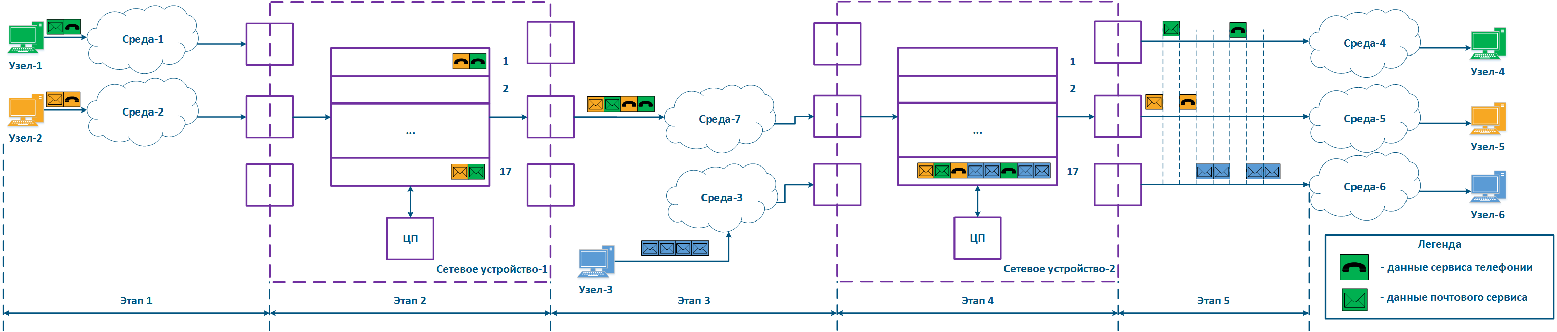
Figure 9a - Example of data distribution with partly implemented QoS policy
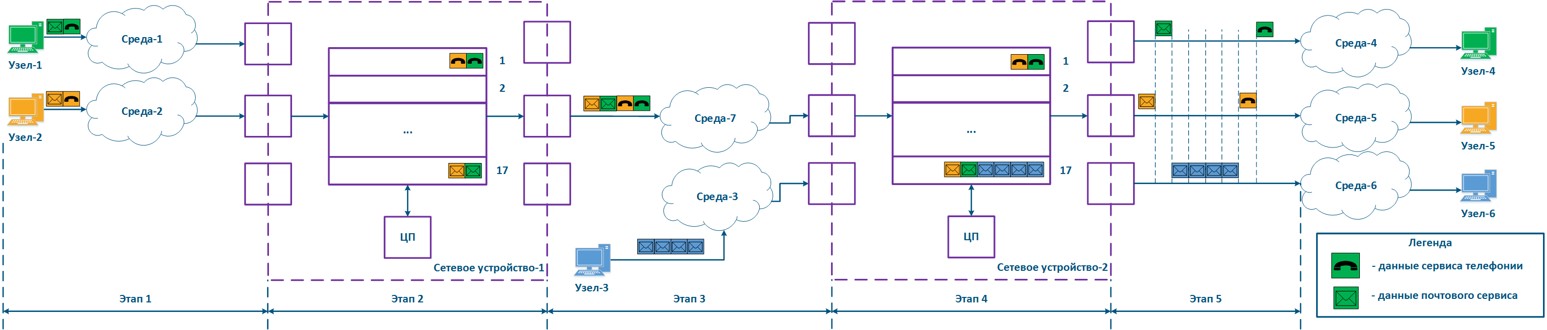
Figure 9b - Example of data distribution with implemented QoS policy
Traffic prioritization mechanism
Traffic transmission path from the management point of view in the network can be described in two ways (Figure 10a, b):
- White-box: all network devices in the data propagation path are in the same responsibility zone. In this case, the QoS configuration on the devices can be synchronized, in accordance with the requirements described in the section above.
- Black-box: some network devices in the data propagation path are in a external responsibility zone. The classification rules for incoming data and the algorithm for putting out packets from queues are configured individually on each device. The architecture of packets queues implementation depends on the equipment manufacturer, therefore there is no guarantee of the correct QoS configuration on devices in external responsibility zone, and as a result, there is no guarantee of the high-quality performance indicators.
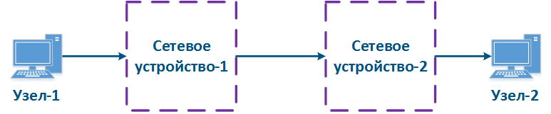
Figure 10a - White-box structure example
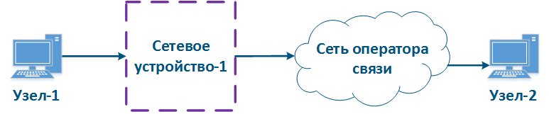
Figure 10b - Black-box structure example
To solve the described problem for the black-box network structure, labeling the packet headers can be performed: the priority required for the packet processing is set in a header field and keeped over the whole path. In this case, all intermediate devices can put incoming data in the queue in accordance with the fields values in which the priority is indicated. It will require the standard protocols development and their implementation by equipment manufacturers.
Keep in mind, usually equipment located in an external responsibility zone does not support data prioritization in accordance with the priority values in the service headers. Traffic priority coordination at the responsibility zones border should be performed at the administrative level.
A processing priority for a packet can be set by the service fields of various network protocols. This article describes the use of Ethernet and IPv4 protocol headers.
Priority within an Ethernet (802.1p)
The Ethernet frame header includes the "User Priority" service field, which is used to prioritize data frames. The field has a 3 bits size, which allows to select 8 traffic classes: 0 class - the lowest priority, 7 class - the highest priority.Keep in mind that the "User Priority" field is only in 802.1q frames, i.e. tagged with the VLAN tag.
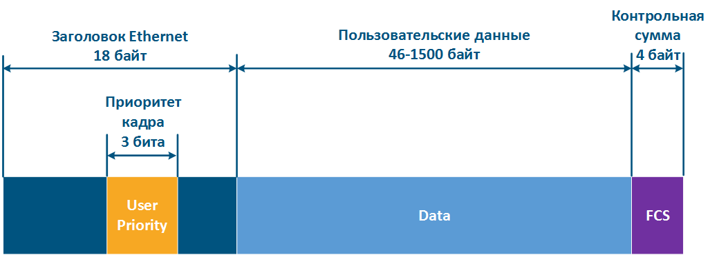
Figure 11 - Frame prioritization service field in Ethernet header
Priority within an IP
IP protocol has three historical stages in the development of the service field responsible for packets prioritization:
- When the protocol was approved, there was an 8-bit ToS (Type of Service) field in the IP packet header (see RFC 791). ToS included the following fields (Figure 12a):
- Precedence: priority value.
- Delay: delay minimization bit.
- Thorughput: throughput minimization bit.
- Reliability: reliability maximization bit.
- 2 bits with values are equal to 0.
- 8 bits were still used for packets prioritization, however, ToS had included the following fields (see RFC 1349):
- Delay.
- Throughput.
- Reliability.
- Cost: bit to minimize the cost metric (1 bit is used, which value was previously zero).
- IP header structure has been changed (see RFC 2474).The 8 bits previously used for prioritization were distributed in a following way (Figure 12b):
- DSCP (Differentiated Services Code Point): packet priority.
- 2 bits are reserved.
Thus, ToS allows to distinguish 8 traffic classes: 0 - the lowest priority, 7 - the highest priority, and DSCP - 64 classes: 0 - the lowest priority, 63 - the highest priority.
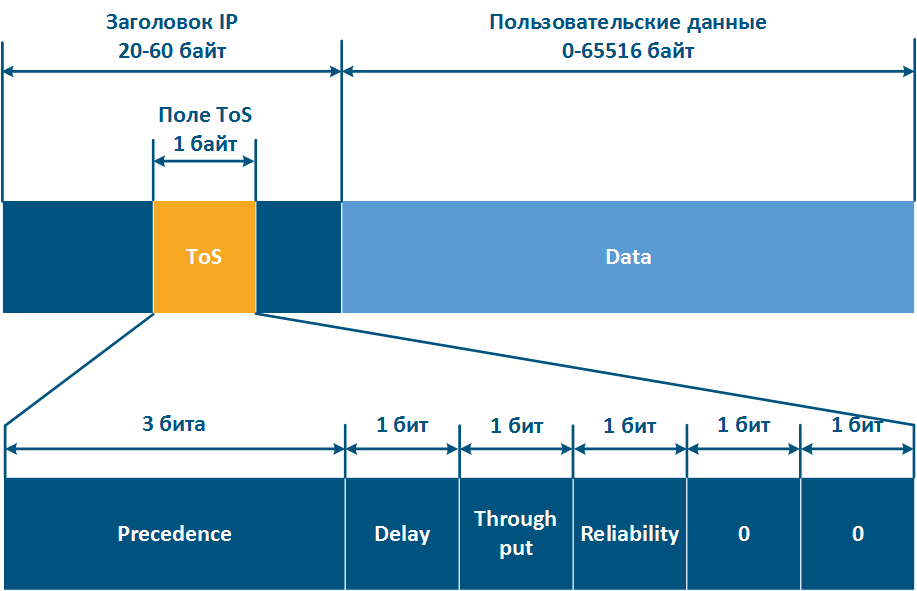
Figure 12a - ToS service field in IP packet header
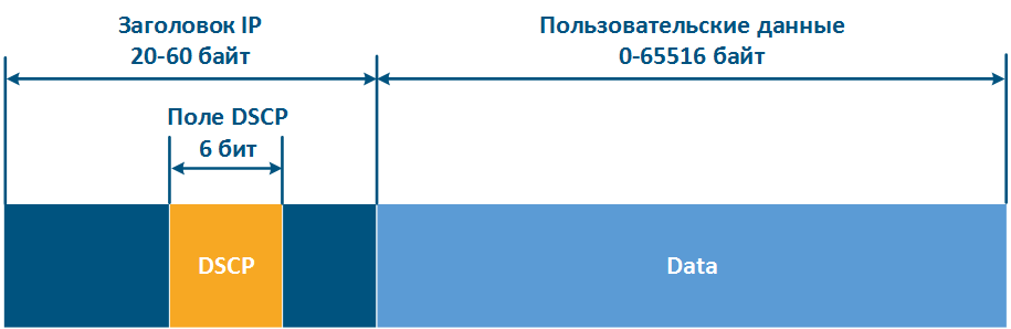
Figure 12b - DSCP service field in IP packet header
Priority configuration
Many end nodes on the network do not support manipulation with service headers: can not set or remove the priority, so this functionality should be implemented on the intermediate network devices.
Let's look at the example of data transmission from Node-1 to Node-2 through a DS-domain and a third-party telecom operator network (Figures 13a-c). The DS domain includes three devices, two of them for the domain are borderline and one is intermediate. Lets look at the steps of processing data in a network using an Ethernet frame transmission (the basic principles discussed in the example are applicable for an IP packet or other protocol that supports data prioritization):
- Этап 1: Узел-1 формирует кадр Ethernet для Узла-2. Поле для установки приоритета кадра в заголовке отсутствует (рис. 13а).
- Этап 2: Пограничное сетевое устройство-1 меняет заголовок Ethernet, устанавливая в поле приоритета значение 1. На пограничных устройствах должны быть настроены правила для выборки трафика Узла-1 из общего потока, для того, чтобы необходимый приоритет был установлен только этим кадрам. В сетях с большим числом потоков трафика список правил на пограничных устройствах может быть объёмным. Пограничное сетевое устройство-1 обрабатывает кадр в соответствии с установленным приоритетом, помещая его в соответствующую очередь сообщений. Кадр передаётся на исходящий интерфейс и отправляется в сторону Промежуточного сетевого устройства-2 (рис. 13а).
- Этап 3: Промежуточное сетевое устройство-2 принимает кадр Ethernet, в котором установлен приоритет 1, и помещает его в соответствующую очередь сообщений. Устройство не выполняет манипуляций по установке/удалению приоритета в заголовке кадра. Кадр передаётся в сторону Пограничного сетевого устройства-3 (рис. 13а).
- Этап 4: Пограничное сетевое устройство-3 обрабатывает входящий кадр аналогично Промежуточному устройству-2 (см. Этап 3) и передаёт его в сторону Сети оператора связи(рис. 13а).
- Этап 4б: в случае, если существует договорённость о том, что трафик будет передан через Сеть оператора связи с приоритетом, отличным от 1, то Пограничное устройство-3 должно выполнить изменение приоритета. В рассматриваемом примере, устройства меняет значение приоритета с 1 на 6 (рис. 13б).
- Этап 5: при распространении кадра через Сеть оператора связи устройства руководствуются значением приоритета в заголовке Ethernet (рис. 13а).
- Этап 5б: аналогично Этапу 5 (рис. 13б).
- Этап 5в: при отсутствии договорённости о приоритизации кадров данных в соответствии со значением приоритета, указанным в заголовке Ethernet, сторонний оператор связи может применить к трафику собственную политику QoS и установить приоритет, который может не согласовываться с политикой QoS, принятой в DS-домене (рис. 13в).
- Этап 6: пограничное устройство в Сети оператора связи удаляет поле приоритета из заголовка Ethernet и передаёт его в направлении Узла-2 (рис. 13а-в).

Рисунок 13а - Пример изменения приоритета кадра Ethernet при распространении через два сегмента сети (приоритет сегментов согласован)
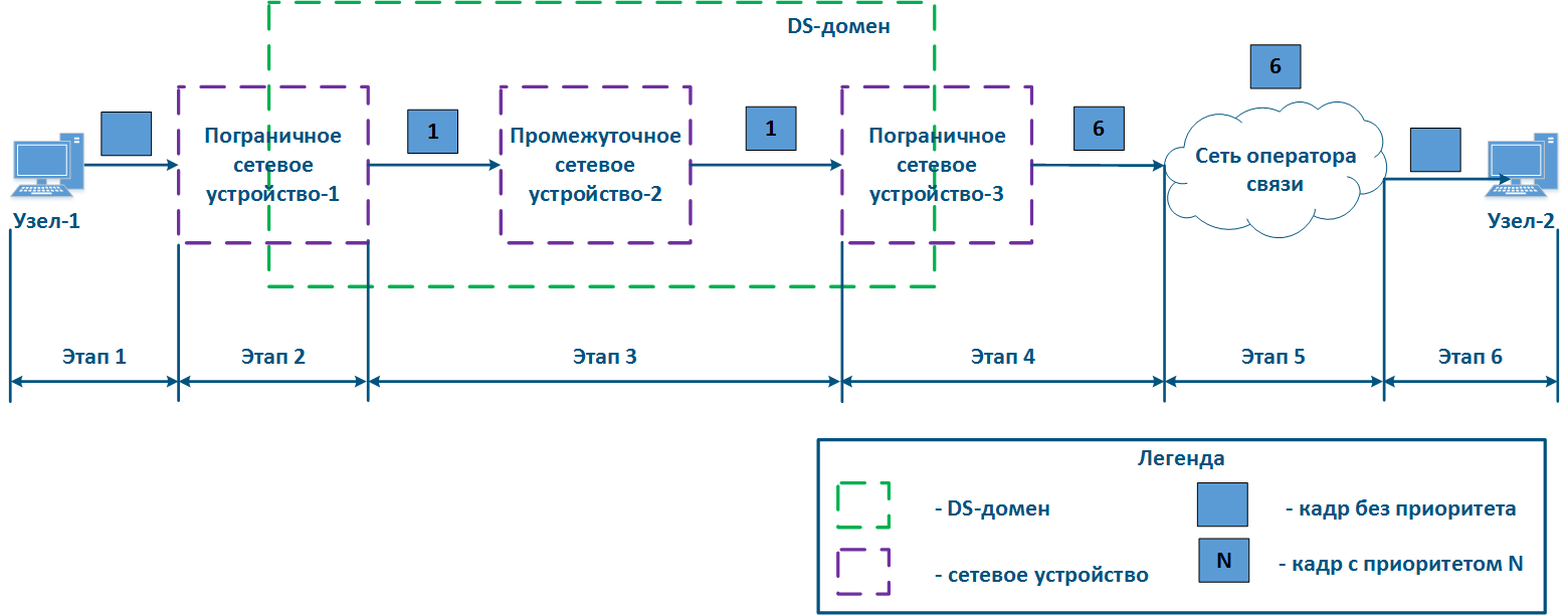
Рисунок 13б - Пример изменения приоритета кадра Ethernet при распространении через два сегмента сети (приоритет сегментов согласован, но должен быть изменён)

Рисунок 13в - Пример изменения приоритета кадра Ethernet при распространении через два сегмента сети (приоритет сегментов не согласован)
Реализация очередей в устройствах Инфинет
Процесс анализа устройством приоритета в служебных заголовках и обработка данных в соответствии с этими приоритетами не является простым по следующим причинам:
- Устройства поддерживают автоматическое распознавание приоритетов в соответствии с разными протоколами. Например, устройства семейства InfiLINK XG поддерживают распознавание приоритетов 802.1p и не распознаёт значения приоритетов DSCP.
- Устройства, являющиеся пограничными для DS-домена, позволяют использовать разный набор критериев для классификации трафика. Например, устройства InfiMAN 2x2 позволяют установить приоритет, выбрав весь TCP-трафик, направленный на порт 23, устройства семейства Vector 5 - нет.
- Число очередей, реализованных в устройствах разных производителей, отличается. Для того, чтобы установить соответствие между приоритетом в служебном заголовке данных и внутренней очередью устройства, должна быть использована таблица соответствия.
Данные о внутренней архитектуре очередей, возможностях управления приоритетами данных и соответствия между протокольными и внутренними значениями приоритетов приведены в таблицах ниже.
Следует отметить архитектурную особенность организации очередей в устройствах Инфинет: все очереди делят между собой единый буфер памяти. В случае, если весь трафик попадает в одну очередь, то её размер будет соответствовать размеру буфера, а если очередей будет несколько, то размер буфера памяти будет равномерно поделен между ними.
Таблица внутренней организации очередей сообщений
| Параметр | Описание | InfiLINK 2x2 / InfiMAN 2x2 | InfiLINK XG / InfiLINK XG 1000 | Vector 5 / Vector 70 |
|---|---|---|---|---|
| Критерий маркировки | Набор критериев, которые могут использоваться при классификации входящего трафика. | поддержка PCAP-выражений (PCAP выражения позволяют выполнить гибкую фильтрацию на основе любых полей служебных заголовков, см. PCAP-фильтры) | vlan-id | vlan-id |
| Автораспознавание | Для указанных протоколов семейство устройств позволяет выполнить автоматическое распознавание приоритета, установленного в заголовке и помещение данных в соответствующую очередь. | RTP 802.1p IPIP/GRE-туннели MPLS DSCP ToS ICMP TCP Ack PPPoE | 802.1p | 802.1p |
| Число очередей | Количество очередей сообщений, используемое в устройстве. | 17 | 4 | 8 |
| Диспетчеризация очередей | Поддерживаемые механизмы выборки сообщений из очередей сообщений. | |||
| Настройка приоритизации в Web | Ссылки на документацию по настройке приоритизации трафика через Web-интерфейс. | Настройка коммутации | ||
| Настройка приоритизации в CLI | Ссылки на документацию по настройке приоритизации трафика через интерфейс командной строки. | Команда qm | Команды настройки коммутатора | - |
Таблица соответствия протокольных и внутренних приоритетов для устройств семейств InfiLINK 2x2, InfiMAN 2x2
| Класс трафика (в соответствии с MINT) | InfiLINK 2x2, InfiMAN 2x2 | 802.1p | ToS (Precedence) | DSCP |
|---|---|---|---|---|
| Background | 16 | 01 | ||
| Regular best effort | 15 | 00 | 00 | 0 |
| Business 6 | 14 | 01 | 8, 10 | |
| Business 5 | 13 | 12, 14 | ||
| Business 4 | 12 | 02 | 16, 18 | |
| Business 3 | 11 | 20, 22 | ||
| Business 2 | 10 | 03 | 24, 26 | |
| Business 1 | 9 | 02 | 28, 30 | |
| QoS 4 | 8 | 04 | 32 | |
| QoS 3 | 7 | 34 | ||
| QoS 2 | 6 | 36 | ||
| QoS 1 | 5 | 03 | 38 | |
| Video 2 | 4 | 04 | 05 | 40, 42 |
| Video 1 | 3 | 44, 46 | ||
| Voice | 2 | 05 | 06 | 48, 50 |
| Control | 1 | 06 | 52, 54 | |
| NetCrit | 0 | 07 | 07 | 56, 58, 60, 62 |
Таблица соответствия протокольных и внутренних приоритетов для устройств семейств InfiLINK XG, InfiLINK XG 1000, Vector 5, Vector 70
| Класс трафика (в соответствии с 802.1p) | 802.1p | InfiLINK XG, InfiLINK XG 1000 | Vector 5, Vector 70 |
|---|---|---|---|
| Background (наименьший приоритет) | 00 | 1 | 0 |
| Best Effort | 01 | 1 | |
| Excellent Effort | 02 | 2 | 2 |
| Critical Applications | 03 | 3 | |
| Video | 04 | 3 | 4 |
| Voice | 05 | 5 | |
| Internetwork Control | 06 | 4 | 6 |
| Network Control (наивысший приоритет) | 07 | 7 |
Диспетчеризация очередей
Приоритизация сообщений подразумевает под собой использование нескольких очередей сообщений, содержимое которых должны быть передано исходящим интерфейсам через единую шину сообщений. Устройства Инфинет поддерживают два механизма передачи сообщений из очередей в шину: строгая и взвешенная диспетчеризация.
Строгая диспетчеризация
Механизм строгой приоритизации подразумевает последовательное опустошение очередей в соответствии со значениями приоритета. Отправка сообщений с приоритетом 2 будет выполнена только после того, как в шину будут переданы все сообщения с приоритетом 1 (рис. 14). После того, как будут отправлены сообщения с приоритетами 1 и 2, устройство начнёт отправку сообщений с приоритетом 3.
Данный механизм имеет явный недостаток: низкоприоритетному трафику не будут выделяться ресурсы, если есть сообщения в более приоритетных очередях, что приведёт к полной недоступности некоторых сетевых сервисов.
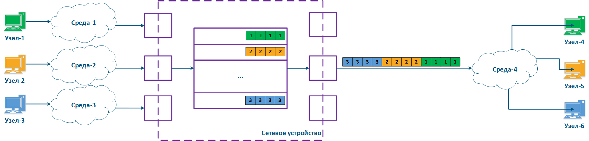
Рисунок 14 - Строгая диспетчеризация сообщений
Взвешенная диспетчеризация
Взвешенная диспетчеризация лишена недостатков строгой диспетчеризации. Взвешенная диспетчеризация подразумевает распределение ресурсов между всеми очередями сообщений в соответствии с весовыми коэффициентами, которые соответствуют значениям приоритета. В случае трёх очередей сообщений (рис. 15), весовые коэффициенты могут быть распределены следующим образом:
- очередь сообщений 1: вес = 3;
- очередь сообщений 2: вес = 2;
- очередь сообщений 3: вес = 1.
При использовании взвешенной диспетчеризации каждая из очередей сообщений получит ресурсы, т.е. не возникнет ситуации с полной недоступностью одного из сетевых сервисов.

Рисунок 15 - Взвешенная диспетчеризация сообщений
Рекомендации по приоритизации трафика
Можно сформулировать набор универсальных рекомендаций по конфигурации механизмов приоритизации трафика:
- Необходимо скрупулезно отнестись к разработке политики QoS. Политика должна описывать трафик всех сервисов, используемых в сети, предусматривать строгое соответствие сервиса и класса трафика.
- Политика QoS должна учитывать технические возможности устройств по распознаванию и манипуляции со значениями служебных полей, в которых указывается приоритет данных.
- На пограничных устройствах DS-домена должны быть настроены правила классификации потоков трафика.
- На промежуточных устройствах DS-домена должна быть активирована функция автоматического распознавания приоритетов трафика.
Механизмы ограничения пропускной способности
Распределение ресурсов сети между потоками трафика может быть выполнено не только за счёт приоритизации, но и с помощью механизма ограничения пропускной способности. В этом случае, скорость передачи данных потока не может превысить пороговый уровень, установленный администратором сети.
Принцип ограничения скорости в устройствах Инфинет
Принцип ограничения скорости заключается в постоянном измерении интенсивности потока данных и, в случае, если значение интенсивности превышает установленный порог, срабатывает ограничение (рис. 16а,б). Для ограничения пропускной способности в устройствах Инфинет используется алгоритм Token Bucket, заключающийся в том, что все пакеты данных сверх порога пропускной способности отбрасываются. В результате образуются потери, описанные выше.
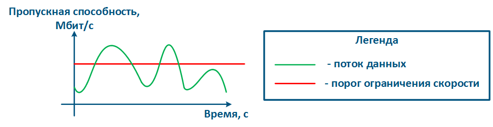
Рисунок 16а - График интенсивности потока данных без ограничения
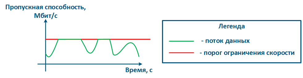
Рисунок 16б - График интенсивности потока данных после ограничения
Алгоритм Token Bucket
Для каждого правила ограничения скорости формируется логический буфер, содержащий объём разрешённых для передачи данных. Как правило, размер этого буфера больше, чем размер ограничений. Каждую единицу времени такому буферу выделяется размер данных, равный установленному порогу ограничения скорости.
В рассматриваемом примере (видеоролик 1) ограничение скорости составляет 3 единицы данных, размер буфера - 12 единиц данных. Буфер постоянно пополняется в соответствии с установленным порогом, однако не может быть заполнен больше собственного объёма.
Видеоролик 1 - Выделение ресурсов буферу ограничения скорости
Обработка данных, поступивших на входящий интерфейс устройства, будет выполнена только в том случае, если буфер содержит ресурсы для их обработки (видеоролик 2). Таким образом прохождение данных опустошает буфер ресурсов. Если в момент прихода данных буфер будет пуст, то данные будут отброшены.
Видеоролик 2 - Использование выделенных ресурсов при обработке данных
Следует понимать, что процессы выделения ресурсов буферу ограничения скорости и обработки данных выполняются одновременно (видеоролик 3).
Интенсивность потоков данных в пакетных сетях непостоянна, что позволяет проявить одно из достоинств алгоритма Token Bucket. Интервалы времени, в которые не передаются данные, позволяют выполнить накопление ресурсов в буфере, а затем обработать объём данных, превышающий порог ограничения. Импульсным потокам данных, например web-трафик, будет выделена широкая полоса, позволяющая выполнить быструю загрузку web-страниц, повысив уровень комфорта конечного пользователя.
Несмотря на описанное преимущество алгоритма Token Bucket, средняя пропускная способность будет соответствовать установленному порогу, т.к. на длительных интервалах времени объём ресурсов будет определяться не размером буфера, а интенсивностью его заполнения, которая соответствует порогу пропускной способности.
Видеоролик 3 - Обработка данных буфером ограничения скорости
Алгоритм Token Bucket может быть применён для отдельных потоков трафика, в этом случае буфер ограничения скорости будет выделен для каждого из потоков (видеоролик 4).
В рассматриваемом примере создано два правила ограничения скорости: для трафика vlan 161 - 3 единицы данных в единицу времени, для трафика vlan 162 - 2 единицы данных. Размер буфера для каждого из потоков трафика равен 4 интервалам времени, т.е. 12 единиц данных для трафика vlan 161 и 8 единиц данных для трафика vlan 162. Суммарно буферам выделяется 5 единиц данных в каждый из интервалов времени, далее выделенные ресурсы распределяются между буферами. Поскольку размер буферов ограничен, то ресурсы, выделенные сверх их размеров, не могут быть использованы.
Видеоролик 4 - Выделение ресурсов двум буферам ограничения скорости
Ресурсы каждого буфера могут быть использованы только для трафика соответствующего сервиса (видеоролик 5). Так, для обработки трафика vlan 161 используется буфер ресурсов для трафика vlan 161. Аналогично используются ресурсы буфера для трафика vlan 162.
Видеоролик 5 - Использование выделенных ресурсов для обработки данных
Существуют способы связи буферов ресурсов друг с другом. Например, в устройствах Инфинет буферы выделенных ресурсов могут быть связаны через классы (см. ниже). В случае, если один из буферов ресурсов будет заполнен (видеоролик 6), выделенные ему ресурсы могут быть предоставлены другому буферу.
В примере буфер для трафика vlan 162 заполнен, что позволяет пополнить буфер трафика vlan 161 выделенными 5 единицами данных, вместо 3. В этом случае пропускная способность сервиса vlan 161 вырастет. Но как только буфер ресурсов трафика vlan 162 появится свободная память, то распределение ресурсов вернётся к нормальному режиму: трафику vlan 161 - 3 единицы данных, трафику vlan 162 - 2 единицы данных.
Видеоролик 6 - Перераспределение выделенных ресурсов между буферами ограничения трафика различных сервисов
Виды ограничений скорости в устройствах Инфинет
Рассмотренный принцип ограничения пропускной способности реализован в устройствах Инфинет двумя способами:
- Ограничение трафика физического интерфейса: ограничение будет применено к суммарному трафику всех потоков данных, проходящих через физический интерфейс. Данный метод прост в конфигурации - следует указать интерфейс и значение порога, но не позволяет применить ограничение к трафику конкретного сетевого сервиса.
- Ограничение потока трафика: ограничение применяется к логическому потоку данных. Логический поток данных выделяется из общего трафика с помощью проверки на соответствие заданным критериям, что позволяет применять ограничения пропускной способности к трафику сетевых сервисов, выбор которых выполняется на основе значений полей служебных заголовков. Например, можно выделить в логический канал весь трафик с vlan 42 и ограничить только его пропускную способность.
Устройства Инфинет позволяют настраивать иерархические структуры распределения ресурсов пропускной способности. Для этого используются два типа объектов: логический канал и класс, которые связаны отношением "потомок-родитель" соответственно. В классе указывается пропускная способность, которая будет распределена между дочерними логическими каналами, а в канале значения гарантированной и максимальной пропускной способностей, CIR и MIR соответственно.
Рассмотрим пример передачи трафика двух сервисов, ассоциированных с идентификаторами vlan 161 и 162, между Master и Slave (рис. 17а). Суммарному трафику сервисов выделено не более 9 Мбит/с.
Конфигурация устройства Master может быть выполнена следующим образом (рис. 17б):
- Создан Класс 16, пропускная способность которого ограничена значением 9 Мбит/с.
- Класс 16 является родительским по отношению к каналам 161 и 162, т.е. сумма трафика этих логических каналов ограничена значением 9 Мбит/с.
- Трафик с идентификатором vlan 161 ассоциируется с логическим каналом 161, vlan 162 - с логическим каналом 162.
- Значения CIR для канала 161 равно 4 Мбит/с, канала 162 - 5 Мбит/с. Если оба сервиса будут активно обмениваться данными, то пороговые значения для их трафика составят CIR, установленные для каждого из каналов.
- Значения MIR для канала 161 равно 9 Мбит/с, канала 162 - 7 Мбит/с. Если трафик в логическом канале 162 будет отсутствовать, то пороговое значение для канала 161 будет равно MIR, т.е. 9 Мбит/с. В обратном случае, пороговое значение для канала 162 будет равно 7 Мбит/с.
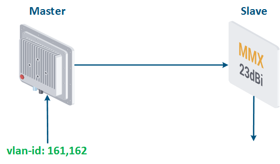
Рисунок 17а - Пример ограничения пропускной способности для трафика c vlan-id = 161, 162
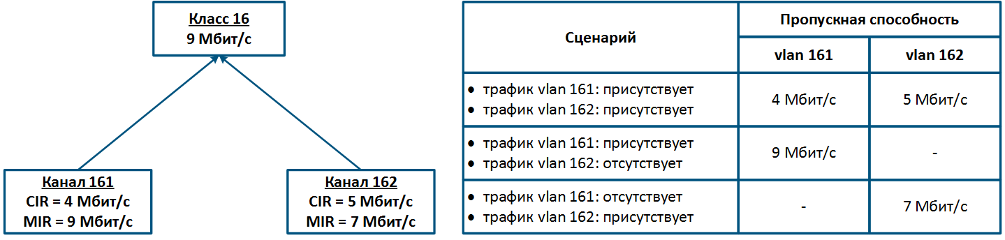
Рисунок 17б - Иерархическая структура каналов ограничения пропускной способности для трафика с vlan 161 и 162
Функциональные возможности по конфигурации ограничения пропускной способности на устройствах Инфинет всех семейств представлены в таблице ниже:
Таблица функциональных возможностей по ограничению пропускной способности в устройствах Инфинет
| Параметр | Описание | InfiLINK 2x2 / InfiMAN 2x2 | InfiLINK XG / InfiLINK XG 1000 |
|---|---|---|---|
| Ограничение на интерфейсе | Возможность ограничения пропускной способности для физического интерфейса устройства. | - |
|
| Ограничение логического потока | Возможность ограничения пропускной способности для потока трафика, выделенного по одному или нескольким критериям. | до 200 логических каналов | - |
| Направление трафика | Возможность применения ограничений к входящему/исходящему потокам трафика. | входящий и исходящий | исходящий |
| Иерархия ограничений | Возможность создания системы взаимных иерархических ограничений. | до 200 классов, являющихся дочерними по отношению к логическим каналам | - |
| Критерии правил логических потоков | Критерии, используемые для выделения потоков данных. | поддержка PCAP-выражений (PCAP выражения позволяют выполнить гибкую фильтрацию на основе любых полей служебных заголовков, см. PCAP-фильтры) | - |
| Настройка ограничений в Web | Ссылки на документацию по настройке ограничений пропускной способности через Web-интерфейс. | Контроль трафика | Раздел Коммутатор |
| Настройка ограничений в CLI | Ссылки на документацию по настройке ограничений пропускной способности через CLI. | Команда qm | Команды настройки коммутатора |
Рекомендации по конфигурации ограничения пропускной способности
При конфигурации ограничения пропускной способности потоков данных следует руководствоваться следующими рекомендациями:
- Следует выполнять ограничение для трафика всех сетевых сервисов. Эти действия позволят сохранить контроль над всеми потоками трафика и осознанно выделять ресурсы для этих потоков.
- Ограничение пропускной способности должно выполняться на устройствах, расположенных ближе всего к источнику данных. Нет необходимости дублировать правила ограничения пропускной способности для потока данных на протяжении всей цепочки промежуточных устройств.
- Многие сетевые сервисы являются двунаправленными, что требует применения ограничений на устройствах как к входящему, так и исходящему трафику.
- Для корректной установки пороговых значений пропускной способности следует предварительно оценить средние и максимальные значения трафика сервисов. Особое внимание следует обратить на часы наибольшей нагрузки. Выполнить сбор данных для проведения анализа можно с использованием системы мониторинга InfiMONITOR.
- Сумма значений CIR логических каналов, ассоциированных с одним классом, не должна быть более максимальной пропускной способности класса.
Дополнительные материалы
White papers
Вебинары
Видео
Прочее
- RFC 4594.
- RFC 791.
- RFC 1349.
- RFC 2474.
- Система мониторинга InfiMONITOR.
- Веб-интерфейс устройств семейств InfiLINK 2x2, InfiMAN 2x2. Параметры QoS.
- Веб-интерфейс устройств семейств InfiLINK 2x2, InfiMAN 2x2. Контроль трафика.
- Веб-интерфейс устройств семейств InfiLINK XG, InfiLINK XG 1000. Настройка QoS.
- Веб-интерфейс устройств семейства Vector 5. Настройка коммутации.
- Веб-интерфейс устройств семейства Vector 70. Настройка коммутации.
- Настройка QoS manager в ОС WANFleX.