Successfully pass the free certification exam at IW Academy and become an Infinet Certified Engineer.
During link planning, such factors as distance, obstacles and the link margin should be taken into account. We strongly recommend to use the InfiPLANNER tool for link planning.
InfiPLANNER
InfiPLANNER is a link planning tool, which allows to design networks using InfiNet Wireless devices for optimal deployment and cost effectiveness. It accounts for different scenarios based on geography, distance, antenna height, transmit power, device models and other factors. It outputs an installation report that defines the parameters to be used for configuration, alignment and operation. Use the installation report to compare the predicted performance with the actual link performance. InfiPLANNER is available at https://infiplanner.infinetwireless.com.
NOTE
You can find more detailed information about InfiPLANNER in the "InfiPLANNER: Link Planning Tool" online course.
Range and obstacles
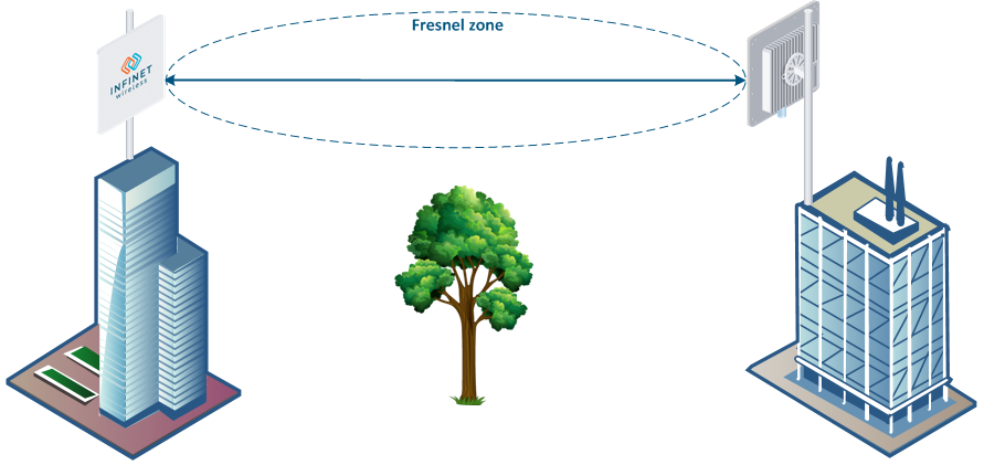
Make sure that line of sight is provided when planning the antennas' placement for a point-to-point link in order to achieve maximum range and performance between two antennas. Perform a survey to identify all the obstructions (such as trees or buildings) in the path and to assess the risk of interference.
The radio beam is an electromagnetic wave and it is not as thin as a laser beam, for example. The main energy in a radio beam is concentrated along the straight line between the two antennas, inside an area with the shape of an ellipsoid (or a rugby ball). This area is called the 1st Fresnel zone and its exact form and size depend upon the frequency and the signal propagation path length.
If most of the 1st Fresnel zone is obstructed, a major part of the radio wave’s electromagnetic energy is lost, which leads to a severe signal quality degradation and as a result to a decreased coverage range or performance.
Below is an incomplete list of possible obstructions along the signal propagation path:
- Neighboring buildings.
- Trees.
- Bridges.
- Power lines.
To obtain the best results, it is necessary to perform a precise analysis of the signal propagation path and possible obstructions that may obstruct the 1st Fresnel zone.
NOTE
More detailed information about radio signal propagation is available at "Wireless Networking Fundamentals" online course.
Antenna Installation
General recommendations for antenna installation:
- Try to keep the LOS clear of obstructions. In case of installations over vegetation and forest, make sure the direct LOS stays above the trees; in urban environments - above the tallest buildings along the radio path.
- The influence of trees can be variable, depending on the season (ice, dew, leaves). Keep in mind that, during spring and summer, leaves can absorb high levels of radio energy. Therefore, when installing during the cold season, over forests and trees without leaves, try to achieve a higher fade margin.
- Before installation, make sure the devices are located outside the area of water streams and splashes formation, which can affect the enclosure for a long time.
- Install antennas as far as possible from other antennas (the recommended distance is at least 2 meters between edges of the antennas).
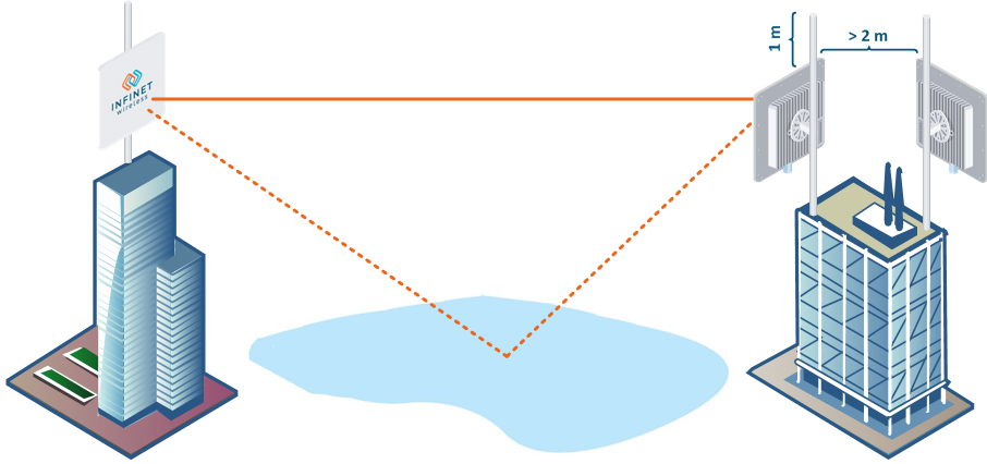
- Reflecting surfaces should be considered (buildings with reflective windows, water surfaces or wet grounds). These can be useful in NLOS situations, if there is no direct clear path between the 2 antennas, so the radio signal needs to be reflected by a surface. However, reflections can also decrease the signal quality when encountered along a clear LOS link, because of fading caused by multipath propagation.
- When installing antennas over the water, tune the height bracket within a 1-3 meters range variation, because it can yield significant signal level variations due to multipath fading.
Spectral aggregation
It is recommended to place base station sectors above the subscriber terminals as high as possible to provide proper antenna tilt in vertical direction and to minimize self-interference. The optimal antenna tilt is defined by the vertical beam width of the sectoral antenna and by the required sector coverage. It must cover all the area, where you plan to deploy the subscriber terminals.
Spectral aggregation should be taken into account when planning composite backhauling links, when installing devices in close proximity to each other on the same pole or in order to implement redundancy and link aggregation. For more information, proceed with the "Link aggregation, balancing and redundancy" article. The devices located close to each other can cause mutual interference. Do not ignore the spectral aggregation rules, otherwise it can lead to a degradation of the wireless links.
The document will provide recommendations on distance and frequency separation for scenarios with and without an external synchronization hub. An external clock source allows you to synchronize the time (the beginning of each second) on multiple devices, up to 7 devices, with an accuracy of less than a microsecond so that all connected devices can turn on the transmitters at the same time. This completely eliminates the mutual influence of neighboring sectors, when one transmitting device with its powerful signal prevents the neighboring device from receiving weak signals from its terminals. Wireless devices synchronization using AUX-ODU-SYNC makes it possible to reuse the frequency within the same base station, that is, different sectors of the same base station can operate on the same frequency channels. When using synchronization, a four-sector base station can operate on only two frequency channels, significantly increasing the real spectral efficiency of the system.
Mutual interference occurs not only between sectors and subscriber terminals of one multi-sector base station, but also between different base stations when they are densely located in a limited frequency range. Synchronization of base stations prevents mutual interference of such base stations and subscriber terminals that working with them.
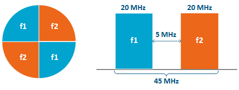
Recommendations for istance and frequency separation for a four-sector ABAB base station are given below.
Without synchronization
Distance separation (vertical or horizontal) must be at least two meters between the edges of the antennas.
Reduce the transmission power.
With synchronization
4 collocated base stations mounted back-to-back.
- The recommended guard interval between the end/boundary frequencies of the occupied bands of the neighboring sectors 5 MHz.
Synchronization settings
To perform synchronization using an external hub, each base station sector must be connected to an AUX-ODU-SYNC.
The following conditions should be met:
- Frame size and DL/UL ratio should be equal on all sync-end units.
- The automatic downlink ratio selection is not allowed.
NOTE
The AUX-ODU-SYNC antenna is not included in the standard packing list. For more information about this antenna, proceed to the AUX-ODU-SYNC article.
Configuration via web interface
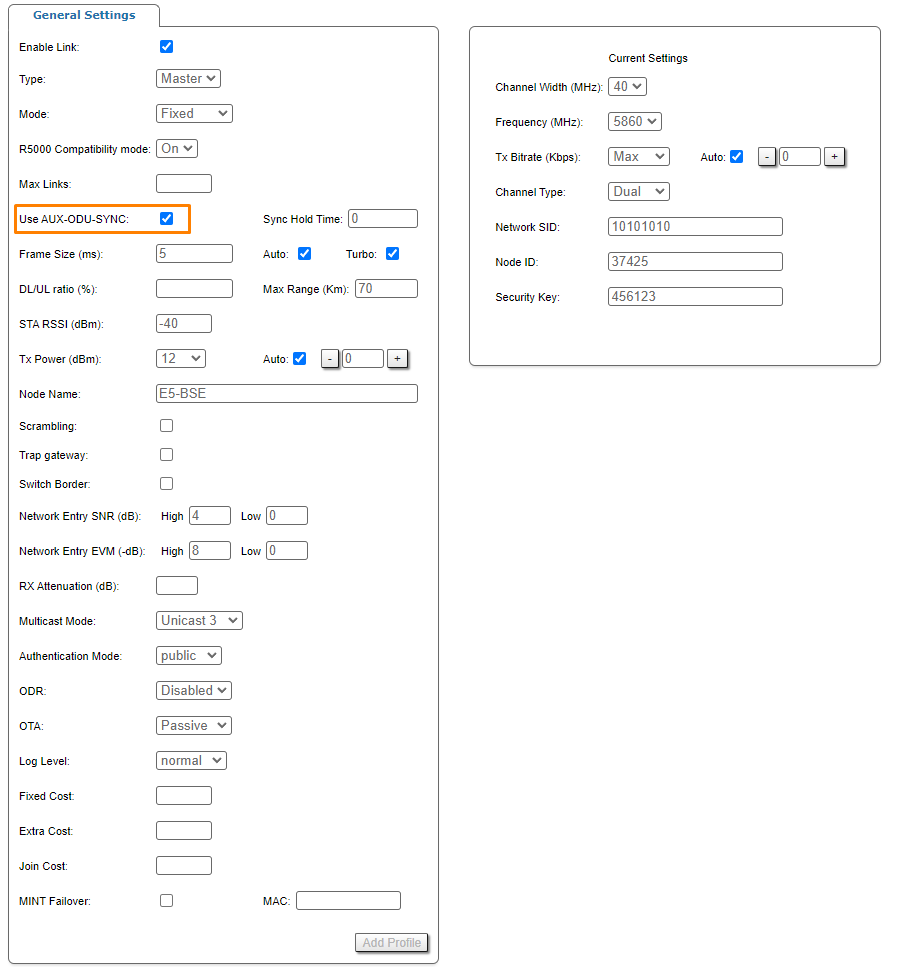
To enable synchronization via web interface:
- Go to the section "Basic Sttings" → "Link Settings" → "rf6.0".
- Check the box "Use AUX-ODU-SYNC" and click "Apply". Synchronization status and the number of visible satellites is displayed in the "Device Status" -> "Link Statistics" section.
Additionally in order to determine the device coordinates GNSS position can be enabled.
Go to the section "Basic Settings" -> "System Settings".
Check the box "Enable GNSS Receiver" and click "Apply" button.
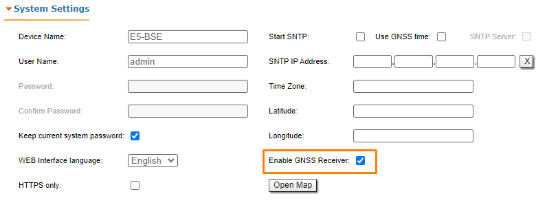
Click "Open map" to view the device location. The map is updated in real time that allows to monitor the movement of the device mounted on the mobile object.
Configuration via CLI
Enable synchronization:
tsync enable
The synchronization mode information:
tsync
The following parameters will be displayed:
| Parameter | Description |
|---|---|
| Status | Current device status |
| Total enabled | Total time during which the synchronizaion unit was enabled |
| Total valid | Total time during which the timing accuracy was better than 10 microseconds |
| Valid time | Time during which the timing accuracy was better than 10 microseconds |
| Last message | Last message from synchronization software |
Additionally in order to determine the device coordinates GNSS position can be enable:
gps start
Detailed GNSS statistic can be obtained:
gps stat
GNSS statistics parameters:
| Parameter | Description |
|---|---|
| Total GPS time | Total time of GPS operation |
| Total nonvalid time | Total time during which the information about coordinates was unavailable |
| Number of losses | Quantity of cases when the information about coordinates had become unavailable |
| Now coordinates are valid last ... | Time of GPS operation since last coordinates discovering |
| Sattelites histogram | Histogram of visible satellites quantity |
| SATmin | Minimum of visible satellites (since the last time you cleared the statistic) |
| SATmax | Maximum of visible satellites (since the last time you cleared the statistic) |