Successfully pass the free certification exam at IW Academy and become an Infinet Certified Engineer.
Rough alignment
Using the azimuth and elevation values computed by the link planning tool roughly position the antenna (in each location) to detect the opposite system signal. Directly before installing the devices we recommend to set up the maximum output power value. If the link cannot be established, try to switch the bitrate to the minimum value and narrowing the channel width. Assess the link establishment and its quality using the LED indicator on the device case. LED indication are detaily described in the Hardware Platform section. For more accurate alignment, use the alignment tool built into the device web interface.
Precise alignment
It is recommended to have two teams prepared for alignment procedure, each team with at least two installers: one should notisy the signal values and communicate with the remote side, the other should make the adjustments with the device. After the initial approximate alignment (link up), the antenna with the lowest gain should be locked into position.
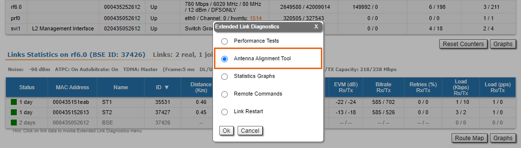
Both teams should use the Antenna Alignment Tool in the Device Status section of the web GUI.
The team at the antenna which has the highest gain will click on the "Start Test" button and start to change the azimuth slowly while watching the signal indicators
- As soon as the best signal has been found (Input Signal stripes must be located in the black area, closer to its center), the antenna must be locked into that position
- The same action will be performed for the elevation, and the antenna must be locked into the final position where both elevation and azimuth provide the best signal, according to the indicators provided by the antenna alignment tool:
- EVM: higher than 21 in absolute value.
- Signal level to interference and noise: higher than 28 dB.
- Retries: lower than 5 %.
CAUTION
No contact should be made with the antennas during signal reading because the human body can affect the radiation pattern of the antenna and signal readings.
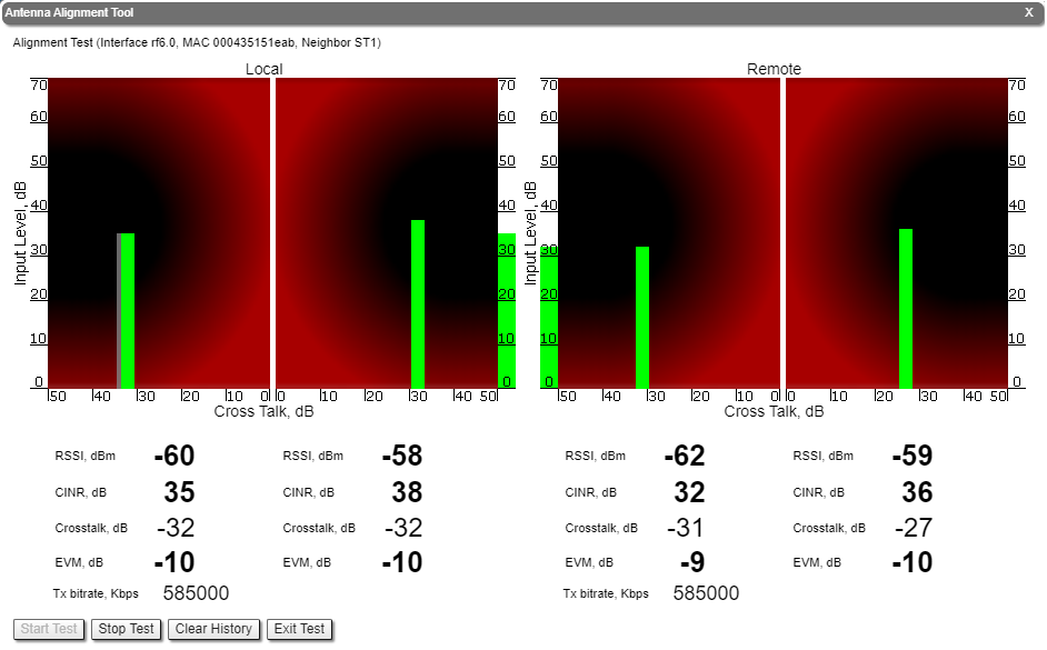
The main parameters displayed in the alignment tool:
- RSSI - indicates the power level of the received radio signal, optimal parameter value -60 ... -40 dBm.
- CINR - input signal level to noise + interference indicator, >=28 dB.
- Crosstalk - indicates how much vertically and horizontally polarized signals influence each other, >20 dB in absolute value.
- Error Vector Magnitude (EVM) - indicator of the measured input signal quality (it should be as high as possible in absolute value, the recommended level is not less than 21 dB in absolute value. Some old firmware had EVM value positive, but most the firmware has negative value, so for the troubleshooting, evaluate the absolute EVM value).
- Tx bitrate - displays the current bitrate for the remote and local units (measured in Kbps).
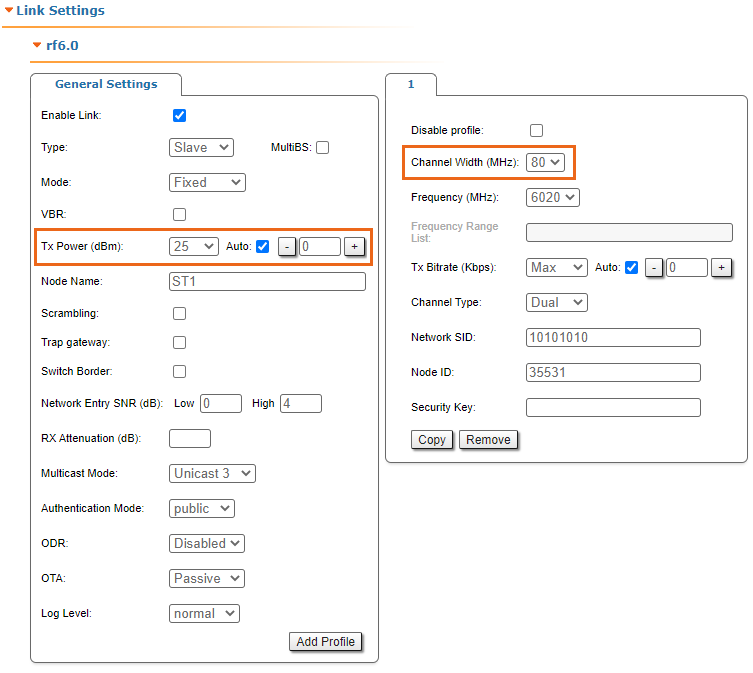
As soon as the antennas have been precisely alignment, set the "auto" option for Tx power and bitrate at both units and select values in accordance with the EIRP limitations.
Depending on the values for SNR, RSSI, retries and current bitrate, change the following parameters:
- Decrease/increase the Tx power level (keeping the auto option checked) to have the SNR at around 25 dB and the RSSI at around -55 dBm.
- Decrease the bandwidth to lower the noise and to increase the SNR to above 20 dB.
Wireless link statistics
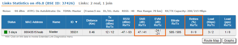
- Let's check the link parameters. Go to the Device Status section and in the Link Statistics, check the following parameters:
- Retries Rx/Tx: maximum 5 %.
- EVM Rx/Tx: not less than 21 dB in absolute value.
- SNR Rx/Tx: not less than 27 dB.
If these conditions are met and the maximum bitrate is reached, the wireless connection quality is good. Otherwise, use the diagnostic tools described in the Device Status article.