Page tree
Skip to end of metadata
Go to start of metadata

Successfully pass the free certification exam at IW Academy and become an Infinet Certified Engineer.

To the certification exam

Switch configuration

The Switch configuration is based on a set of rules for the switching groups:

  • An unique numeric identifier (1-4999) for each group
  • Two or more local network interfaces (ethX, rfX, tunX, etc) and a set of rules (filters) which allow placing different types of traffic into different switching groups
  • Each node can have several switching groups. The same interfaces or group of interfaces can be used in several groups simultaneously
  • Switching groups are activated on different nodes of the MINT network. The nodes that have the same switching group identifier in their configurations represent a "switching zone"
  • "Switching zone" exists only within the MINT network segment.

Switching groups

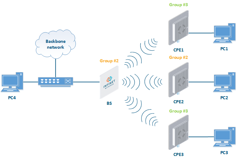
The MINT network can be viewed as one virtual distributed layer-3 switch, where border nodes act as external ports of the virtual switch. The virtual switch task is to transport frames from one external port to another. It is important to understand that switching groups should be created only on the nodes where frames enter from or leave to the "outside" network ("outside" relative to MINT). On the repeater nodes (in mesh topology) there is no need to create switching groups.

Figure - Switching Groups

In order to put an incoming frame into one of the switching groups, a set of flexible rules is used, which allow sorting frames according to various criteria, like:

  • VLAN tag
  • Protocol type
  • Addresses (MAC/IP)
  • Ports
  • Any PCAP expressions.

Trunk groups

Trunk group is a switching group in the "Trunk" mode.

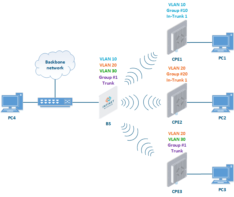
Input flow from wired segment for trunk group is divided into separate sub-groups (switching groups within trunk group) depending on VLAN-tag of the packet. The group number of the switching group within trunk group will be equal to the VLAN-number of packets which are switched to it.

The trunk groups are used for the ease of configuration, when VLAN flows are transmitted to several subscribers.

If you enable the trunk group at the BS side to transmit several VLAN-flows to several directions, then at the CPE side, you should use the "In-Trunk" option to specify the group number of the trunk group that includes the required switching group.

Figure - Trunk Groups

Trunk groups may also be used to solve the task of connecting several VLAN segments.

Special rules on interfaces allow flexible manipulations with VLAN ID tags: deleting, assigning and re-assigning (please consult the information provided in WANFleX OS User Manual).

Management connection to the unit

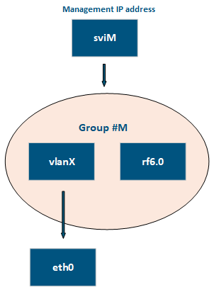
For the management purposes, you can create a dedicated Switch Group for all units in the MINT network, attached to the Switch Virtual Interface (SVI). Assign the IP addresses directly on the SVI interface for native management. All packets sent via SVI interface will be distributed only within the assigned switch group.

The universal way to configure Management VLAN via dedicated switch group is presented in the figure below (for more information see section "Remote management of the InfiLINK 2x2, InfiMAN 2x2, InfiLINK Evolution and InfiMAN Evolution units").

You have to assign the Management IP addresses to "sviM" interface which is the management interface of Group M and includes "vlanX" (with parent interface "eth0") and "rf6.0" interface:

Figure - Management configuration

Switch Group rules

Once assigned to one of the switching groups, a frame will never leave it until it reaches one of the external ports. Switching group rules are applied only when the frame enters to MINT network through one of its external ports. When leaving the network, no rules are required as the frame already belongs to one of the switching groups and it is automatically forwarded to an external port(s) that belongs to the corresponding switching group.

NOTE

Frames originated by MINT network nodes (for example: containing RIP/OSPF, ping packets, etc) do not belong to any of the switching groups. Therefore, they cannot leave MINT network via switching through any of the external ports.

Rules are used for the following purposes:

  • Selecting an appropriate switching group when a packet is received through "ethX" interface. The packet is switched by the group the rules of which it fully satisfies.

CAUTION

 A packet that cannot be associated with any switching group will not switched by the device. If there is no group with appropriate rules for the packet, it is discarded.

  • When the packet is assigned to a switching group, the group decides whether the packet to be sent through one of the interfaces, or to discard it. The packet will only be sent if it satisfies the rules of this interface.

The rules consist of a "rules list" and a decision (deny/permit). While parsing the list, the switch checks whether a packet matches the rule. If it matches the rule, the decision set for this rule is applied to the packet. Otherwise, the list of rules is viewed further. Rules are taken one at a time. If a packet does not match to any rule, the default decision for this group or interface is taken.

The expression selects which packets will fit into the group. Only the packets for which the expression is “true” will be matched to the group. The expression consists of one or more primitives. Primitives usually consist of an id (name or number) preceded by one or more qualifiers.

Examples packet filter rules:

Single IP subnet:

 net 192.168.1.0/24

Several IP subnets:

 net 192.168.1.0/24 or net 192.168.100.0/24

Several IP subnets with exceptions:

net 192.168.1.0/16 and not net (192.168.100.0/24 or 192.168.200.0/24)

Several IP subnets inside VLAN:

vlan 50 and (net 192.168.1.0/24 or net 192.168.100.0/24)

PPPoE traffic:

pppoed or pppoes

which is synonym to:

ether proto 0x8863 or ether proto 0x8864

Disable IP multicast and broadcast:

not ip multicast

Detailed filter expression syntax description

The filter expression determines which packets are selected by the filter for further processing. If no expression is given, all the packets on the net are selected. Otherwise, only the packets for which expression is “true” are selected.

There are three different kinds of qualifier:

QualifierDescription
type
  • Qualifiers say to what the id name or number refers to
  • Possible types are: host, net, port, portrange
  • For example: “host foo”, “net 128.3”, “port 20”, “portrange 6000-6008”
  • If there is no type qualifier, host is assumed
dir
  • Qualifiers specify a particular transfer direction to and/or from id
  • Possible directions are: src, dst, src or dst and src and dst
  • For example, “src 1.1.1.1”, “dst net 128.3”, “src or dst port 21”. If there is no dir qualifier, src or dst is assumed
proto
  • Qualifiers restrict the match to a particular protocol
  • Possible protos are: ether, ip, ip6, arp, rarp, tcp and udp
  • For example: “ether src 00:12:13:14:15:16”, “arp net 128.3”, “tcp port 21”, “udp portrange 7000-7009”
  • If there is no proto qualifier, all protocols consistent with the type are assumed
  • For example, “src 1.1.1.1” means “(ip or arp or rarp) src foo” (except the latter is not legal syntax), “net 1.2.3.0/24” means “(ip or arp or rarp) net 1.2.3.0/24” and “port 53” means “(tcp or udp) port 53”
Table - Qualifiers

More complex filter expressions are built up by using the words “and”, “or” and “not” to combine primitives. For example: “host foo and not port ftp and not port ftp-data”. To save typing time, identical qualifier lists can be omitted. For example: “tcp dst port ftp or ftp-data or domain” is exactly the same as “tcp dst port ftp or tcp dst port ftp-data or tcp dst port domain”.

Allowable primitives are:

PrimitivesDescription
dst host host
  • True if the IPv4 destination field of the packet is "host", which may be either an address or a name
src host host
  • True if the IPv4 source field of the packet is "host"
host host
  • True if either the IPv4 source or destination of the packet is host
  • Any of the above host expressions can be prefixed with the keywords, ip, ip6, arp, rarp as in: “ip host host
  • This is equivalent to: “ether proto \ip and host host”
ether dst ehost
  • True if the Ethernet destination address is "ehost"
  • Ehost must have a numeric format: XX:XX:XX:XX:XX:XX
ether src ehost
  • True if the Ethernet source address is "ehost"
ether host ehost
  • True if either the Ethernet source or destination address is "ehost"
dst net net
  • True if the IPv4 destination address of the packet has a network number of "net"
src net net
  • True if the IPv4 source address of the packet has a network number of "net"
net net
  • True if either the IPv4 source or destination address of the packet has a network number of "net"
net net mask netmask
  • True if the IPv4 address matches net with the specific netmask. May be qualified with "src" or "dst"
net net/len
  • True if the IPv4 address matches net with a netmask "len" bits wide
  • May be qualified with "src" or "dst"
dst port port
  • True if the packet is ip/tcp, ip/udp and has a destination port value of "port"
src port port
  • True if the packet has a source port value of "port"
port port
  • True if either the source or destination port of the packet is "port"
dst portrange port1-port2
  • True if the packet is ip/tcp, ip/udp and has a destination port value between "port1" and "port2"
  • "port1" and "port2" are interpreted in the same fashion as the port parameter for "port"
src portrange port1-port2
  • True if the packet has a source port value between "port1" and "port2"
portrange port1-port2
  • True if either the source or destination port of the packet is between "port1" and "port2"
  • Any of the above port or port range expressions can be prefixed with the keywords, tcp or udp, as in: “tcp src port port
  • This matches only tcp packets whose source port is "port"
less length
  • True if the packet has a length less than or equal to "length"
  • This is equivalent to: “len <= length
greater length
  • True if the packet has a length greater than or equal to "length"
  • This is equivalent to: “len >= length
ip proto protocol
  • True if the packet is an IPv4 packet of protocol type "protocol"
  • Protocol can be a number or one of the names icmp, icmp6, igmp, igrp, pim, ah, esp, vrrp, udp, or tcp
  • The identifiers tcp, udp, and icmp are also keywords and must be escaped via backslash (\), which is \\ in the C-shell
  • This primitive does not chase the protocol header chain
ip protochain protocol
  • True if the packet is IPv4 packet, and contains protocol header with type protocol in its protocol header chain
  • For example, “ip protochain 6” matches any IPv4 packet with TCP protocol header in the protocol header chain
  • The packet may contain, for example, authentication header, routing header, or hop-by-hop option header, between IPv4 header and TCP header
  • The code emitted by this primitive is complex and cannot be optimized, so this can be somewhat slow
ether broadcast
  • True if the packet is an Ethernet broadcast packet
  • The ether keyword is optional
ether multicast
  • True if the packet is an Ethernet multicast (or broadcast) packet
  • The "ether" keyword is optional
  • This is shorthand for “ether[0] & 1 != 0
ip multicast
  • True if the packet is an IPv4 multicast (or broadcast) packet
ether proto protocol
  • True if the packet is of ether type protocol
  • Protocol can be a number or one of the names ip, ip6 ,arp, rarp, atalk, aarp, sca, lat, mopdl, moprc, iso, stp, ipx, or netbeui
  • These identifiers are also keywords and must be escaped via backslash (\)
  • In the case of Ethernet, WANFleX checks the Ethernet type field for most of those protocols
  • The exceptions are:
    • iso, stp, and netbeui
      WANFleX checks for an 802.3 frame and then checks the LLC header as it does for FDDI, Token Ring, and 802.11
    • atalk
      WANFleX checks both for the AppleTalk etype in an Ethernet frame and for a SNAP-format packet as it does for FDDI, Token Ring, and 802.11
    • aarp
      WANFleX checks for the AppleTalk ARP etype in either an Ethernet frame or an 802.2 SNAP frame with an OUI of 0x000000
    • ipx
      WANFleX checks for the IPX etype in an Ethernet frame, the IPX DSAP in the LLC header, the 802.3-with-no-LLC-header encapsulation of IPX, and the IPX etype in a SNAP frame
ip, arp, rarp, atalk, aarp, iso, stp, ipx, netbeui
  • Abbreviations for “ether proto p”, where “p” is one of the above protocols
svlan [vlan_id]
  • True if the packet is an IEEE 802.1Q Service VLAN packet (ether proto 0x88a8)
vlan [vlan_id]
  • True if the packet is an IEEE 802.1Q VLAN packet (ether proto 0x8100)
  • If [vlan_id] is specified, only true if the packet has the specified vlan_id
  • The first "vlan" or "svlan" keyword encountered in expression changes the decoding offsets for the remainder of expression on the assumption that the packet is a VLAN packet
  • The "vlan" "[vlan_id]" expression may be used more than once, to filter on VLAN hierarchies
  • Each use of that expression increments the filter offsets by 4
  • For example, “svlan 100 && vlan 200” filters on VLAN 200 encapsulated within Service VLAN 100, and “vlan 300 && ip” filters IPv4 protocols encapsulated in VLAN 300, and “svlan 100” filters all packets encapsulated within Service VLAN 100
mpls [label_num]
  • True if the packet is an MPLS packet
  • If [label_num] is specified, only true is the packet that has the specified label_num
  • The first "mpls" keyword encountered in expression changes the decoding offsets for the remainder of expression on the assumption that the packet is a MPLS-encapsulated IP packet
  • The "mpls" "[label_num]expression may be used more than once, to filter on MPLS hierarchies
  • Each use of that expression increments the filter offsets by 4
  • For example, “mpls 100000 && mpls 1024 “ filters packets with an outer label of 100000 and an inner label of 1024, and “mpls && mpls 1024 && host 192.9.200.1” filters packets to or from 192.9.200.1 with an inner label of 1024 and any outer label
pppoed
  • True if the packet is a PPP-over-Ethernet Discovery packet (Ethernet type 0x8863)
pppoes
  • True if the packet is a PPP-over-Ethernet Session packet (Ethernet type 0x8864)
  • The first "pppoes" keyword encountered in expression changes the decoding offsets for the remainder of expression on the assumption that the packet is a PPPoE session packet
  • For example, “pppoes && ppp proto 0x21” filters IPv4 protocols encapsulated in PPPoE
tcp, udp, icmp
  • Abbreviations for: “ip proto p”, where “p” is one of the above protocols
iso proto protocol
  • True if the packet is an OSI packet of protocol type protocol
  • Protocol can be a number or one of the names clnp, esis, or isis
clnp, esis, isis
  • Abbreviations for: “iso proto p”, where “p” is one of the above protocols
expr relop expr
  • True if the relation holds, where relop is one of >, <, >=, <=, =, !=, and expr is an arithmetic expression composed of integer constants (expressed in standard C syntax), the normal binary operators [+, -, *, /, &, |, <<, >>], a length operator, and special packet data accessors
  • Note that all comparisons are unsigned, so that, for example, 0x80000000 and 0xffffffff are > 0
  • To access data inside the packet, use the following syntax: “proto [ expr : size ]”   
  • Proto is one of ether, fddi, tr, wlan, ppp, slip, link, ip, arp, rarp, tcp, udp, icmp, and indicates the protocol layer for the index operation (ether, fddi, wlan, tr, ppp, slip and link all refer to the link layer)
  • tcp, udp and other upper-layer protocol types only apply to IPv4
  • The byte offset, relative to the indicated protocol layer, is given by expr
  • Size is optional and indicates the number of bytes in the field of interest; it can be one, two, or four, and defaults to one
  • The length operator, indicated by the keyword len, gives the length of the packet
  • For example, “ether[0] & 1 != 0” catches all multicast traffic
  • The expression “ip[0] & 0xf != 5” catches all IPv4 packets with options
  • The expression “ip[6:2] & 0x1fff = 0” catches only unfragmented IPv4 datagrams and frag zero of fragmented IPv4 datagrams
  • This check is implicitly applied to the "tcp" and "udp" index operations
  • For instance, "tcp[0]" always means the first byte of the TCP header, and never means the first byte of an intervening fragment
  • Some offsets and field values may be expressed as names rather than as numeric values
  • The following protocol header field offsets are available: icmptype (ICMP type field), icmpcode (ICMP code field), and tcpflags (TCP flags field)
  • The following ICMP type field values are available: icmp-echoreply, icmp-unreach, icmp-sourcequench, icmp-redirect, icmp-echo, icmp-routeradvert, icmp-routersolicit, icmp-timxceed, icmp-paramprob, icmp-tstamp, icmp-tstampreply, icmp-ireq, icmp-ireqreply, icmp-maskreq, icmp-maskreply
  • The following TCP flags field values are available: tcp-fin, tcp-syn, tcp-rst, tcp-push, tcp-ack, tcp-urg
Table - Primitives

Primitives may be combined using:

  • A parenthesized group of primitives and operators (parentheses are special to the Shell and must be escaped)
  • Negation (`!' or `not')
  • Concatenation (`&&' or `and')
  • Alternation (`||' or `or').

Negation has highest precedence. Alternation and concatenation have equal precedence and associate left to right. Note that explicit and tokens, not juxtaposition, are now required for concatenation. If an identifier is given without a keyword, the most recent keyword is assumed. For example, “not host 1.1.1.1 and 2.2.2.2” is short for “not host 1.1.1.1 and host 2.2.2.2” and should not be confused with “not (host 1.1.1.1 or 2.2.2.2)”.

MAC Switch Group parameters

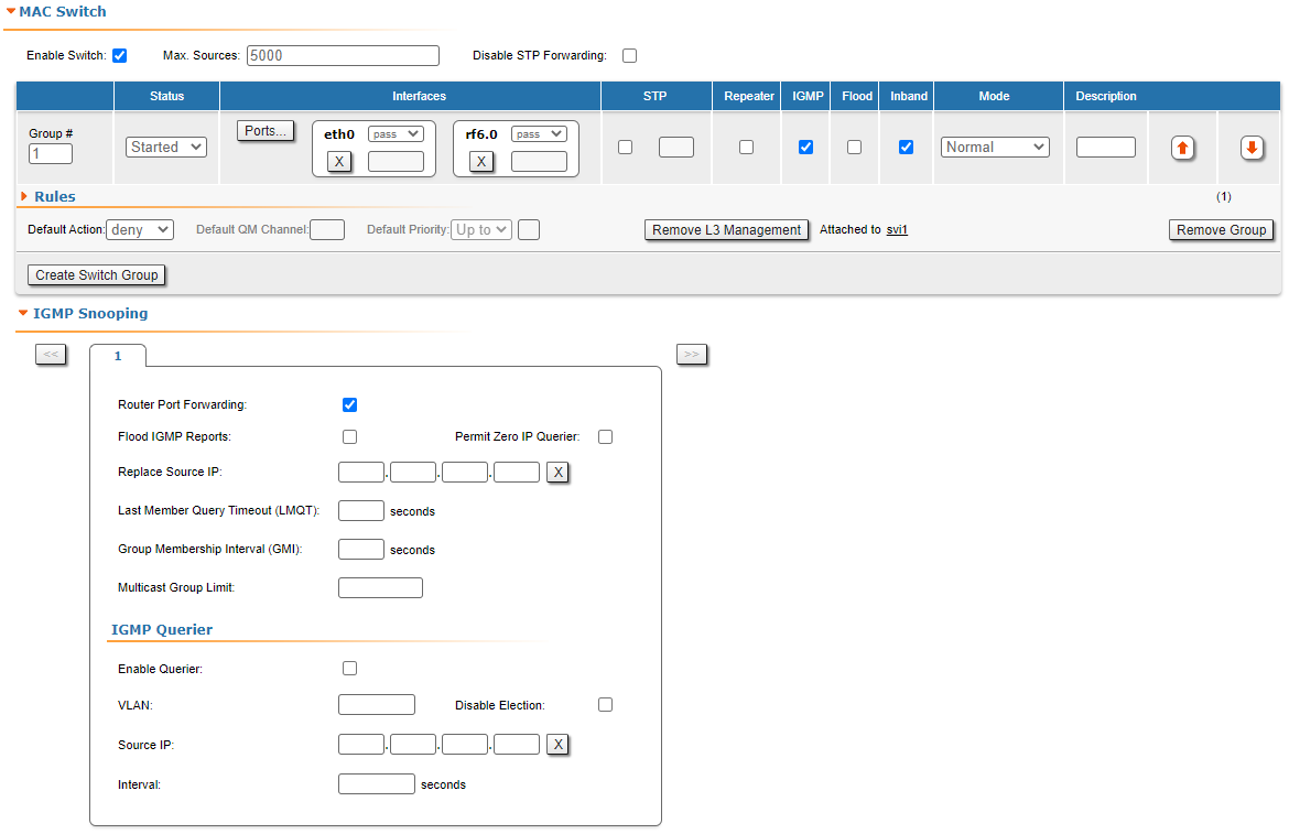
 In the "MAC Switch Group parameters" section, you can view the Switch Groups and Rules that are already created, including the management switch group; you can change the parameters for these Switch Groups, delete them by clicking the «Remove Group» button or create new ones by clicking the «Create Switch Group» button. The same operations are available for the switching rules: add a new rule within a switch group by clicking the «Add Rule» button (located within sub-menu "Rules" of this group) or delete an existing rule by clicking the «Remove Rule» button.

Figure - MAC Switch configuration

General options in this section: 

  • «Enable Switch» - this checkbox enables/disables global switch operation

CAUTION

 Disabling the switch in the absence of routing settings can lead to termination of packet transmitting through the device.

  • "Disable STP Forwarding" - prevents STP frames forwarding in the switch mode when STP support is disabled.
  • "STP MINT mode" - enables/disables the STP MINT mode. STP MINT mode is used to exclude the wired switches with the enabled STP protocol influence on the network operation. The mode blocks the BPDU frames of the STP protocol configured on wired switches so that the switch cannot detect the loop and block its ports. STP MINT mode in conjunction with the RSTP protocol enabled in the Infinet devices allows to break the loop and support the PRF protocol functioning that operates through the wired segment.
  • «Remove L3 Management» - by clicking this button you can delete the "sviX" interface, which is available in the default configuration, for the unit management.
  • «Create L3 Management» - by clicking this button you can add an "sviX" interface for the unit management via Web interface.

«Switch Group configuration» section:

Switch parameterDescription
Group #
  • Displays the Switch Group number
  • Assign the switch group identifier (must be unique within the MINT network segment)
Status
  • Select the Switch Group status: started, stopped or discard
Interfaces
  • Add Ethernet or/and Radio as Switch Group interface(s)  via the «Ports» button
  • "Select": pass (selected by default), strip or tag for VLAN tag modification for each added interface
  • The Interfaces section provides the means to control the VLAN tag processing mode, as each local interface supports three different scenarios:
  • "Pass" - transparent mode, traffic remains unchanged.
  • "Strip" - all tags are stripped.
  • "Tag" - all packets are tagged with the specified VLAN tag
  • Another option in this field is to remove one or both added interfaces
STP
  • Add an STP VLAN number in case that spanning tree support is enabled
Repeater
  • Enable/disable repeater support
  • The unit acts as a simple switch, relaying packets to all ports, except the source port
IGMP
  • Enable/disable IGMP snooping support
  • Please refer to the information provided in the next section for details
Flood
  • Allow/deny unlimited unicast flood without protection filter
Inband
  • Allow/deny access to the device through in-band broadcast/multicast management traffic
  • It is enabled by default
Mode
  • Set the working mode of the switching group: normal, trunk, in-trunk (give it the trunk group number created on the BS), upstream, downstream
  • Normal (standard mode) - the switch group operation is based on the configured Rules, packets are processed without modification (this is the default option)
  • Trunk - the inbound traffic is untagged and placed into switch groups in accordance with its VLAN tag
  • In-Trunk - allows filtering out the traffic that belongs to a certain switch group that is a member of a trunk Switch Group
  • Upstream - used mainly in video surveillance systems for upstream multicast flows
  • Downstream - used in video surveillance systems for downstream traffic
Description
  • Type a description sentence for the current switch group
Default Action
  • Set the default action: permit/deny
  • In the absence of any Switching rule, or if a packet does not match to any Switching rule, the default action for this group or interface is taken
Default QM Channel
  • Allocate a default logical channel
  • The default logical channel must be prior created in the "Traffic Shaping⁣" section
  • In the absence of any Switching rule, or if a packet does not match to any Switching rule, the default logical channel is allocated
  • For the indications on how to create a logical channel, please refer to the "Traffic Shaping" section below
Default Priority
  • Allocate the default priority for all the packets going through the Switch group:
    • Up to” - used to increase the packet priority to the specified value only if the processed packet has a lower priority
    • Set” - used to assign a new priority regardless of the value already assigned to the packet
  • In the absence of any Switching rule, or if a packet does not match to any Switching rule, the default priority is allocated
Table - MAC Switch

You can change the list order of the switch group using the "up/down" arrows.

A set of rules are applied to all packets within a switch group. You can create several switch rules within a switch group. The following parameters are available for switch rules:

Switch Rules parameterDescription
Action
  • Set the action for the packets that match this rule: permit/deny
QM Channel
  • Allocate a logical channel if there are logical channels prior created in the "Traffic Shaping⁣" section
  • If you allocate a number for a logical channel that was not prior created in the "Traffic Shaping" section, it has no effect in the rule configuration
  • For the indications how to create a logical channel, please refer to the "Traffic Shaping" section below
Priority
  • Allocate the priority for all the packets going through the new rule of the filter:
    • Up to” is used to increase the packet priority to the specified value only if the processed packet has a lower priority
    • Set” is used to assign a new priority regardless of the value already assigned to the packet
Packet capture filter
  • Set the packet capture filter for Switching
  • The syntax is called “PCAP expression”
  • Please refer to filter expression syntax description above
  • Validate rule by clicking the «Validate» button
VLAN list
  • Set the VLAN ID
  • It is available for the legacy configuration
  • It can be set also in "PCAP expression" option (for example: VLAN 100 when “PCAP expression” is chosen), PCAP expressions cannot be used in "trunk/in-trunk mode"
  • Validate rule by clicking the «Validate» button
Table - Switch Groups Rules

NOTE

 In all three types of filters: Switching, IP Firewall and Traffic Shaping, there is the same syntax called “PCAP expression” for setting a rule. It is a universal tool for creating filters.

IGMP Snooping

In this section you can set the IGMP-parameters for the groups for which support of IGMP snooping is enabled (the IGMP check box is marked for these groups in the "MAC Switch" section).

Figure - IGMP snooping configuration

IGMP Snooping is a multicast constraining mechanism that runs on Layer 2 devices to manage and control multicast groups. By listening to and analyzing IGMP messages, the device running IGMP Snooping establishes mappings between ports and multicast MAC addresses and forwards multicast data based on these mappings.

In order for IGMP snooping to function, a multicast router must exist on the network and generate IGMP queries. The tables created for snooping (holding the member ports for each a multicast group) are associated with the multicast router. Without a multicast router, the tables are not created and snooping will not work. Furthermore, IGMP general queries must be unconditionally forwarded by all switches involved in IGMP snooping.

IGMP Snooping parameters can be set within "MAC Switch" section:

IGMP Snooping parameterDescription
Router Port Forwarding
  • Enable/disable forwarding to router ports
Flood IGMP Reports
  • Enable/disable flood IGMP reports to all bridging ports, not only to router ports
Permit Zero IP Querier
  • Allow/deny query requests with source address 0.0.0.0
Replace Source IP
  • Replace source IP in all IGMP reports/query packets
Last Member Query Timeout (LMQT)
  • Set the timeout (in seconds)
Group Membership Interval (GMI)
  • Set the interval (in seconds)
Multicast Group Limit
  • Set the limit number for the multicast group
Enable Querier
  • Start/stop the IGMP querier
VLAN
  • Set the IGMP querier VLAN ID in case of a VLAN broadcast domain
Disable Election
  • Enable/disable the IGMP querier election process
Source IP
  • Set the IP address of the IGMP querier
  • By default, this is 0.0.0.0
Interval
  • Set the IGMP querier send interval (in seconds)
Table - IGMP Snooping