Successfully pass the free certification exam at IW Academy and become an Infinet Certified Engineer.
Make sure that the connectivity is provided between the control center and the device's installation point. If the access is missing only for the InfiNet device, further actions must be performed at the device's installation site.
Indicators
Pay attention to the LED indicators on the device's enclosure.
NOTE
The LED indication on the device can be disabled administratively. Make sure there is no "system no indicator" command in the last saved device configuration. We recommend to save backup configurations to the internal memory of the device and to a folder on your PC. The device can store 8 configuration backups. When saving the current configuration, its previous version is automatically added to the backup list with record number 0. All operations with the device configurations are performed using the "config" command.
If the power and Ethernet indicators are off, check the integrity of the power supply, the Ethernet cables and the RJ-45 connectors. Replace the power supply and the cables if necessary.
R5000-Mmx, R5000-Qmx and R5000-Omx
The R5000-Mmx, R5000-Qmx, and R5000-Omx have two LED indicators (red and green) located in the console port. These indicators help to monitor the device's status during the installation. The correspondence between the state of the indicators and the current device state is shown in the table below.
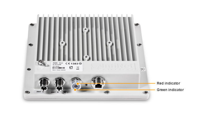
| Red indicator | Green indicator | Device status |
|---|---|---|
| Off | Off | The device is switched off or in the process of start-up booting |
| Off | Blinking | The device has booted, but it has no radio connection. Searching for another device to establish the radio connection |
| Blinking | On | Radio connection established. The more data is being transmitted through the radio channel the more frequently the red indicator is blinking |
R5000-Smn and R5000-Lmn
The R5000-Smn and R5000-Lmn devices have a special LED indicator set located at the back of each device, displaying the current device state.
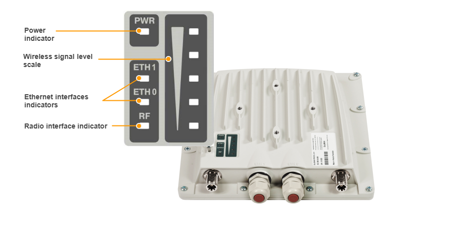
| Indicator | Status | Device status |
|---|---|---|
| PWR | On | The device is powered on |
| RF | Blinking | The RF-link is being established |
| On | The RF-link is established | |
| ETH | On | Wired link established |
| Signal level | This scale displays the current RF signal level and is designed to provide assistance for the radio link alignment and to estimate the link quality. The scale is based on the SNR RX level, with the threshold values for the indicator: 4, 8, 16, 30, 40 dB. The more often the indicator flashes, the better is the quality of the connection. |
Access recovery
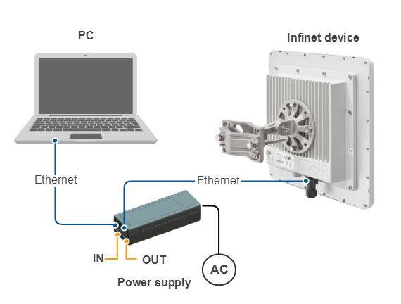
If the power indicator is on and there is connection via the Ethernet interface, connect to the device directly as it is shown in the scheme below. Make sure that the IP address of the PC is in the same subnet as the IP address of the device. You can restore the IP address and reset the device to the factory settings using the ERConsole utility.
The factory reset process using the ERConsole is described in the "Emergence Repair Console" article.
Checking the status of the Ethernet interface
Wired interface statistics
Web interface
If you were able to access the device by connecting directly, try to determine the possible reason for the unavailability through the network. Pay attention to the wired interface statistics. In order to do this, go to the "Device status" section of the web interface and open the "General statistics" window for the Ethernet interface in the "Interface statistics" section. Pay attention to the CRC errors number, as they indicate a violation of the data integrity during the transmission over the wired segment. Also, the problem can be caused by a queue overflow or an inappropriate frame size (Out of range).
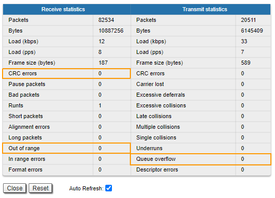
The description of the parameters for a complete diagnostic is available in the "Device status" article.
Command line interface
If there is no access to the device's web interface, run the "ifconfig eth0" command to get statistics via CLI.
The description of the parameters for a complete diagnostic is available in the "Ifconfig command (interfaces configuration)" article.
Duplex mode
Pay attention to the duplex mode on the network devices connected to the wireless router. This information is available in the the web interface. Proceed to the "Device status" section - "Interface statistics" and open the "General statistic" for the Ethernet interface, or run the "ifconfig eth0" command in the command line interface.
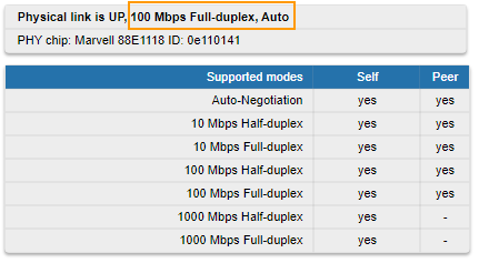
We recommend to set the auto-negotiation mode provided by the Ethernet standard. The problem can occur due to the connection between two devices with different duplex settings. For example, if one device is in auto-negotiation mode and the other is in fixed full duplex mode.
Red value of this parameter in the interface statistics "Mode" column informs that transmission is performed in a half-duplex mode.