Detailed information about each R5000-Smn part number you can find at InfiNet Wireless web-site: InfiLINK 2x2 (PtP products) and InfiMAN 2x2 (PtMP products)
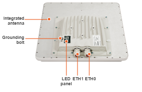
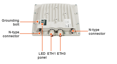
InfiNet Wireless R5000-Smn units top views with indicator panels are below:
|
|
Device status description according to LED modes is given in section "ODU LED indicators description".
Detailed information about each R5000-Lmn part number you can find at InfiNet Wireless web-site: InfiLINK 2x2 (PtP products) and InfiMAN 2x2 (PtMP products).
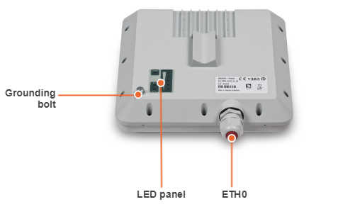
InfiNet Wireless R5000-Lmn units top view with indicator panel is below:
|
Device status description according to LED modes is given in section "ODU LED indicators description".
Detailed information about each R5000-Qmxb part number you can find at InfiNet Wireless web-site: InfiMAN 2x2 (PtMP products).
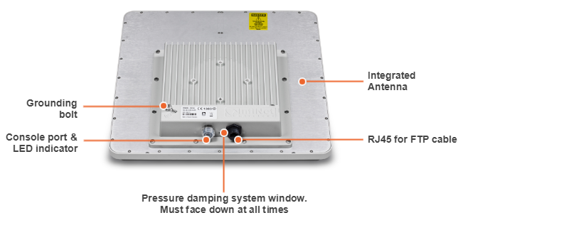
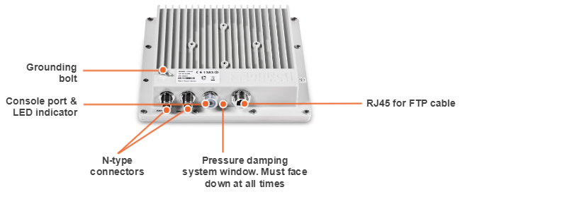
InfiNet Wireless R5000-Qmxb units front panel view is below:
|
Device status description according to LED modes is given in section "ODU LED indicators description".
Detailed information about each R5000-Mmx part number you can find at InfiNet Wireless web-site: InfiLINK 2x2 (PtP products) and InfiMAN 2x2 (PtMP products).
InfiNet Wireless R5000-Mmx units front panel view is below:
|
Device status description according to LED modes is given in section "ODU LED indicators description".
Detailed information about each R5000-Omx part number you can find at InfiNet Wireless web-site: InfiLINK 2x2 (PtP products) and InfiMAN 2x2 (PtMP products).
InfiNet Wireless R5000-Omx units front panel view is below:
|
Device status description according to LED modes is given in section "ODU LED indicators description".
R5000-Qmxb, R5000-Mmx and R5000-Omx models have two LED indicators (red and green) located in the Console connector. These LEDs are useful in monitoring the device status during the installation procedure. LEDs modes and Device status correspondence is shown in the following table:
|
R5000-Smn and R5000-Lmn models have a special LED indicator set located at the back of each device designed to provide basic status information:
|